v4.2 designed by Peter JAKAB in 2004-2005
old version in December, 1999
NOTE for beginners: PICs are general purpose microcontrollers which have to be programmed before you can use them in the actual circuit! Check out this link to learn more.
If you are looking for walkie-talkie or RF circuits, please check here (this page has nothing to do with walkie-talkie circuits).
 RF transmitter, built-in antenna |
 same RF transmitter with external antenna |
 RF receiver, 4 channels |
 same receiver PCB with IR module |
|
This
is a general purpose remote control project with using programmable PIC
microcontrollers. Schematics are shown for using infrared (RF) or radio
(RF) media. If you are not familiar with microcontroller programming,
you can use fixed encoder and decoder integrated circuits instead.
Well-known such IC-s are Holtek HT-12D, HT-12E and Motorola MC145026,
MC145027, MC145028.
Remote controls usually consist
of encoder/decoder parts connected to a transmitter/receiver module
which takes
care of the transmission of digital signals by radio or
infra waves. The format of this project's signal is designed
to be ideal even for the cheapest ASK RF modules (using 50%
signal/silence ratio), and it is similar to the Philips RC-5 format
used in infrared
remote controls. The transmitter has a varying number of
buttons and sends the states of these inputs to the
receiver. The receiver device decodes the message and
sets the outputs accordingly. |
 general schematic for remote controls |
There are two different methods for encoding/decoding channel information:
Current
devices have 4 or 8 channels -
it means they are capable of controlling the state of 4 or 8 switched
outputs. Each transmitter and receiver has an address, and the
transmitter address must
match the address of the receiver to control the channels. The
transmitters are
capable of sending three different types
of codes for the available channels:
All the receivers have an indicator LED
showing that a valid packet was received. Receivers can have different
type outputs for each channel:
| transmitter channel type code | receiver channel type | resulting behaviour |
| simple code | momentary | the channel output is turned ON while the corresponding
transmitter button is pressed, and turned OFF when the button is
released |
| simple code | latched | the channel output state is toggled each time its button is pressed: when the corresponding transmitter button is pressed, the output is turned on. By pressing the same button again, the channel output is turned off |
| channel ON | latched | the channel output is turned on when the corresponding transmitter button is pressed |
| channel OFF | latched | the channel output is turned off when the corresponding transmitter button is pressed |
Current choice of devices:
| name | channels and types | addresses | source code |
| 4-channel RF/IR transmitter | 4 channels, 8 buttons - each
channel has 2 buttons: ON and OFF (for latched receiver operation) |
16 (4-bit) | 4-ch
RF 4-ch IR |
| 8-channel RF/IR transmitter | 8 channels, 8 buttons (for toggle or momentary receiver operation) | 16 (4-bit) | 8-ch
RF 8-ch IR |
| 8-channel RF/IR receiver | 8 channels: each channel can be latched or momentary | 16 (4-bit) | 8-ch
RF 8-ch IR |
| 4-channel RF/IR receiver | 4 channels: each channel has both momentary AND latched outputs (2 outputs per channel) | 16 (4-bit) | 4-ch
RF 4-ch IR |
| The
transmitter has 8 buttons. The 8-channel transmitter can be used for
controlling 8 channels
by sending simple codes, the 4-channel transmitter can be used with
four ON and four OFF buttons for 4
channels. The diode wires (J1-J4) determine the transmitter address.
The number of channels (and button functions) depends on the PIC
code used. |
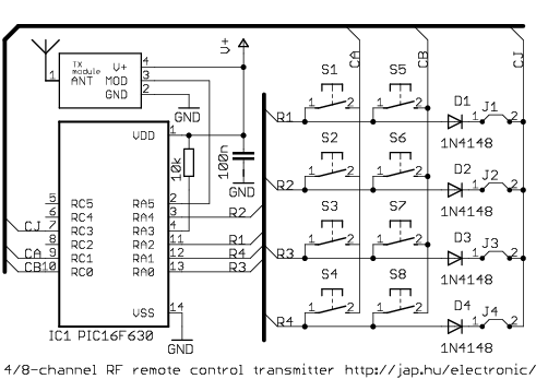 RF transmitter schematic |
| The transmitter has 8 buttons. The 8-channel transmitter can be used for controlling 8 channels by sending simple codes, the 4-channel transmitter can be used with four ON and four OFF buttons for 4 channels. The diode wires (J1-J4) determine the transmitter address. The number of channels (and button functions) depends on the PIC code used. |  IR transmitter schematic |
| The
receiver has 8 relay-switched NO/NC outputs for 8 channels. Each
channel can be set to momentary or latched operation. The address is
set by switch S1. The schematic shows the RF version of the receiver,
the IR version differs only in the receiver module - a 3-pin IR
receiver IC, like TSOP1738 is used |
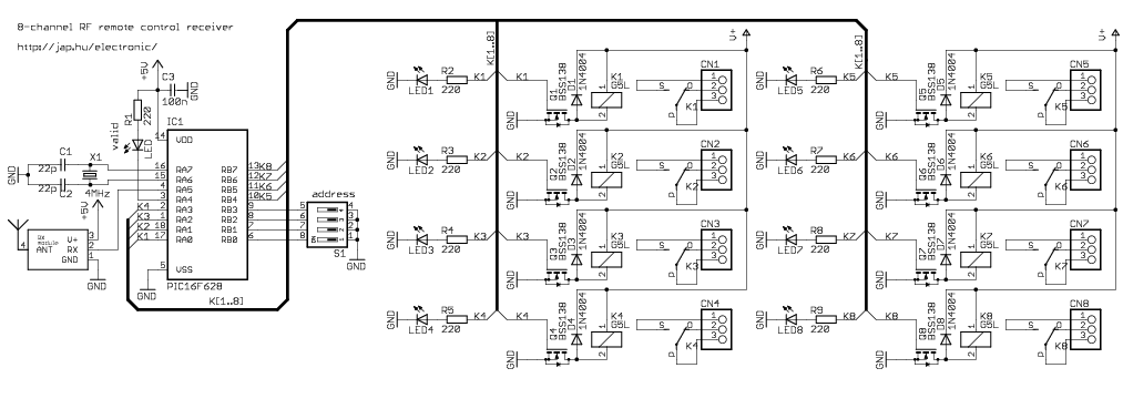 8-channel RF receiver schematic |
| The receiver has 4 or 8 relay-switched NO/NC outputs for 4 channels. Each channel has both momentary AND latched outputs (2 outputs per channel). LM[0-3] outputs are latched outputs of channels, and LM[4-7] outputs are momentary outputs of channels. The 4-relay PCB can be re-wired to select momentary or latched output for the four relays. The address is set by switch S1. The schematic shows the RF version of the receiver, the IR version differs only in the receiver module - a 3-pin IR receiver IC, like TSOP1738 is used | ||
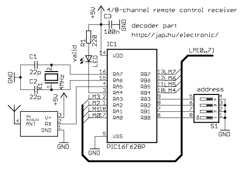 4/8-channel RF receiver schematic, decoder part |
 4-channel RF/IR receiver schematic, relays | |
| It is possible, but not easy to construct a working RF transmitter or receiver.
High frequency circuits need special expertise
and equipment so I recommend that you buy a working RF
module. I used the following devices: HX1000 transmitter, RX1010
receiver
from RFM
and small PCB panels: RF-EZ transmitters, RX-3302 super-regenerative
receiver, Telecontrolli sup-reg and super-heterodyne receivers. The RF
modules are available from a lots of
companies. Here is a list of companies from Oricom:
Laipac, Linx,
IMST,
Glolab,
Semelab,
Sage, Axonn, Lincast,
Abacom, Ramsey, Orbit, Innomedia,
RF Innovations,
Radiometrix,
OKWElec,
Temic,
Telecontrolli,
Lemos, Unilink,
TrueBlue,
Parallax,
Computronics,
VideoComm,
Rentron
(schematics), RFM |
|
 434M RF transmitter modules: RF-EZ STM series, TM01DS, 15-980TX |
 434M RF receiver modules: RX-3302, Telecontrolli RR8-434 |
The RF transmitter modules can use a wide range of input voltages,
so transmitter V+ varies by module specs. Higher RF module voltages
usually result
in greater transmission distances. IR diodes start working at 2.2VDC,
so at least 3V should be applied to the IR version devices. The
microcontrollers can work on voltages 2-5.5VDC, lower voltages result
in smaller current consumption and longer battery life. The
receiver modules (RF and IR) usually take fixed +5VDC, this is already
shown on the RF/IR schematics. The relay driver part can use a higher
voltage, depending on the relay ratings. Standard voltages for receiver
V+ are
12VDC, 6VDC.
All the devices use new, FLASH-based microcontrollers, this means that they can be re-programmed many times. You can experiment with the source code settings to fit your needs. The code can be compiled under MPLAB v5 or v6, but a linked project is required. Please check FAQ at the PIC page.
| source
file |
line | meaning |
| enc-042.asm | 25 #define MODE_CH4 | the
device is 4-channel, sending ON/OFF channel codes |
| enc-042.asm |
28 #define MODE_CH8 | the device is 8-channel,
sending simple codes for channels |
| irmtxv4.asm | 44 pwm_freq EQU d'38000' | the IR transmitter frequency is set to 38000 Hz. This should match the receiver module frequency |
| dec-043.asm | 36
LATCH_MASK EQU 0xff |
select outputs to be latched. This is a binary mask, one bit per channel. Other channels will be momentary |
| dec-044.asm | 38 LATCH_MASK EQU 0xff | |
| mrxv4.asm | 56
#define SKL btfsc 57 #define SKH btfss |
normal decoder logic input is used for the RF receivers (most times) |
| mrxv4.asm | 60
#define SKL btfss 61#define SKH btfsc |
inverse decoder logic input is used for the IR receivers (most times) |
Q: The code doesn't compile! Please send me the HEX
A: Make a linked project.
Here is how to do it in MPLAB v5.
Create a project (project/new) and in the project files area select the root
node (HEX file). Click node properties, select MPLINK as language tool.
Enter appropriate linker file name (eg 16f628.lkr) into additional command
line options. Close window. Click add node to add all the source files one
by one. Place the specified lkr file (eg 16f628.lkr) in the directory
containing the sources. The linker file can usually be copied from your
mplab(/lkr) program directory. Choose the file matching your processor.
MPLAB v6: Start the new project wizard, and when asked, add all assembly,
header files and the linker script to the project.