RE-PSR28A6
rev4.1.1
Three
types of multi-functional Homebrew 6/8Amps, 20- and 30 Ampere
regulatable power supplies:
RE PSR28A68, PSR30A20 and PSR30A30
RE-PSR28A6
rev4.1.1
By Guy, de ON6MU
This is an easy to make power supply which has stable, clean and
regulatable output voltage. By using two 2N3055 transistors we
become more then 2 times the amount of amps then the power supply
delivers, making it real though to brake ;). Although you could
use this design to deliver 20 amps (with some modifications, see
below page), I did not needed such much power. Make sure you
mount them on a huge heat sink, as the 2N3055 transistors can get
very hot at full load. Also use thick wires.
Although the LM-317 power regulator will kick in on shortcircuit, overload and thermal overheating, the fuses in the primary section of the transformer and the fuse F2 at the output will secure your power supply. The rectified voltage of: 30 volt x SQR2 = 30 x 1.41 = 42.30 volt measured on C1. So all capacitors should be rated at 50 volts. Caution: 42 volt is the voltage that could be on the output if one of the transistors should blow.
P1 allows you to 'regulate' the output voltage to anything between 0 and 28 volts. The LM317 lowest voltage is 1.2 volt. To have a zero voltage on the output I've put 3 diodes D7,D8 and D9 on the output of the LM317 to the base of the 2N3055 transistors. The LM317 maximum output voltage is 30 volts, but using the diodes D7,D8 & D9 the output voltage is approx 30v - (3x 0.6v) = 28.2volt.
Calibrate your build-in voltmeter using P3 and, of course, a good digital voltmeter.
P2 will allow you to set the limit of the maximum available amps at the output +Vcc. When using a 100 Ohm/1watt varistat the current is limited to approx. 3 Amps @ 47 Ohm and +- 1 Amp @ 100 Ohms.
Note:
The collectors of the finals needs to be soldered with a wire all
together if the transistors even if they are isolated from the
heatsink or not. If you do not isolated the finals from the
heatsink, then please make sure the heatsink does not make
contact with the chassis (metal casing where you plan to build
the PS into).
Remember to use thick wires suitable for transfering the current
needed according to the power supply you tend to build.
RE-PSR28A68 Power supply Schematic 1
Part list for 6/8 Amp regulatable power supply (PSR28A68):
2 x 15 volt (30volt total) 6+- amps
D1...D4 = four MR750 (MR7510) diodes (MR750 = 6 Ampere diode) or 2 x 4 1N5401 (1N5408) diodes.
F1 = 1 Amp
F2 = 10 amp
R1 2k2 2,5 Watt
R2 240 ohm
R3,R4 0.1 ohm 10 watt
R7 6k8
R8 10k
R9 47 0.5 watt
R10 8k2
C1,C7,C9 47nF
C11 22nF
C2 two times 4700uF/50v
C3,C5 10uF/50v
C4,C6 100nF
C8 330uF/50v
C10 1uF/16v
D5 1N4148, 1N4448, 1N4151
D6 1N4001
D10 1N5401
D11 LED
D7, D8, D9 1N4001
IC1 LM317
Two 2N3055 transistors
P1 5k
P2 47 Ohm or 220 Ohm 1 watt * (be sure you can reach 0 ohms as any resistance limits the current)
P3 10k
trimmer
Calibration:
- Get your hands on a calibrated digital meter or a
good analog meter and measure the voltage at the output
of the power supply.
- Turn P1 to maximum (maximum voltage of our power
supply).
- Adjust P3 till the meter needle shows maximum result
(end scale)
- If you want to calibrate the scale, turn P1 to several
voltages (like every volt) and confirm each time with
your calibrated voltage meter. Make a mark on your power
supply meter-scale to calibrate the meter.
- You should see equal spaced voltage marks on your
home-made scale if your meter is a linear type.
Less maximum
output voltage needed?
In operation, the LM317 develops a nominal 1.25V reference
voltage, VREF, between the output and adjustment terminal.
The reference voltage is impressed across program resistor R1
and, since the voltage is constant, a constant current I1 then
flows through the output set resistor R2, giving an
output voltage of

Since the 100 uA
current from the adjustment terminal represents an error term,
the LM317 was designed to minimize IADJ and make it very constant
with line and load changes.
To do this, all quiescent operating current is returned to the
output establishing a minimum load current requirement. If there
is insufficient load on the output, the output will rise.
Less amps
needed?
Well, without much modification you can:
- only one 2N3055, will give you 4...5 amps.
- the bridge rectifier (D1...D4) only needs 4 x 1N5401 (any +/- 3
amp diodes as only halve of the max. amp is needed, so we have
some room when short-circuited)
- one 4700uF (C2) is sufficient
- F2 = 6 amp
- D5, D10 = 1N4001
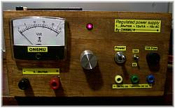
The power supply
insides

Heat
sink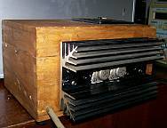 |
Remember to
isolate the transistors from the chassis/radiator! Use a
radiator (heat sink) of appropriate size and surface
area; insulating and heat-conducting spacer or at least a
thin mica; hot adhesive and thermal paste. |
Finished power
supply:

Note: You can add a 3th 2N3055 and use for R9=27 Ohm, to make a 10/12 ampere power supply of the design stated above.
Mark, PA4M, made a
3 ampere version by using just one 2N3055 and build into a Zetagi
power supply box. He reported a very good linearity of the output
voltage over the entire range.


 Thanks Mark for the feedback and
pictures!
Thanks Mark for the feedback and
pictures!
20 ampere regulatable power supply
1...30volt
RE-PSR30A20
(total revision)
RE-PSR30A20
Schematic 2

Major revision of the entire project.
PSR30A20/30 Specs
1.35 volt ... 30 volts
20 ampere PSR30A20 (modify up to 30 amps PSR30A30)
voltage stabilisation
low ripple
short-circuit protection
option: current regulation
HF immunity
Today's
highlight!
Part
list PSR30A20 or PSR30A30
20/30 Ampere regulatable power supply (30
amp version values in blue):
2 x 14 volt 20+- amps (30 amps)
F1 = 2 Amp (4 amp)
F2 = 25 amp (35 amp)
R1 2k2 - 2,5 Watt
R2 240 ohm
R3,R4,R5,R6 0.1 ohm 10 watt
R7 6k8
R8 10k
optional:
R9: 47 Ohm 1 watt. Higher values limits the amps even
more. Experiment!
(or 4watt potentiometer for adjustable output amps, but
be sure you can reach 0 ohms as any resistance limits the
max. output current)
optional S2 mini switch (silver plated)
R10: 10
R11 4k7
C1,C7,C9 47nF
C2 five X
4700uF/50v or one 22000uF/50v
C2
seven X 4700uF/50v or one 22000uF/50 + 10000uF/50v
C3 10uF/50v
C5 1uF/50v
C4,C6,C10 100nF
C8 220uF/50v
C10 4.7uF/16v
C11 2n2
C12 22nF
(C13,C14...100nF optional when using a metal chassis where the zero volt is islolated from)
C15 100nF
C16 10nF
D1...D4=
Bridge rectifier MB2504 (25 amps cooled)
or eight BYW29 8 amp diodes (TO220 pinning cooled)
or 8 x MR750 (MR7510) diodes (MR750 = 6 Ampere diode) or
16 x 1N5401 (1N5408) diodes.
D5, D8 1N4148 (1N4448, 1N4151)
D7 1N4001
D10 1N5401
D11 LED
IC1 LM317
Q1...Q4: Four 2N3055 transistors (six 2N3055)
Q5 BC338, 2N2222, BC547
P1 5k
P3 10k trimmer
optional: relay = 30 volts AC, 2x10 (3x10) amp switching
Optional (and can be left out together with R9) S2, which switches between +- 5 Amps and full output current. R9 can be replaced by a 47 or even a 100 ohms potentiometer of 4watt for adjustable output amps, but be sure you can reach 0 ohms as any resistance limits the max. output current!
The relay is used to switch off the power supply voltage when the mains (S1) are/is switched off. So no delay do to the discharge of C2, and so preventing output voltages from not return to zero immediately. You can leave it out if you do not care about slow discharge of the voltage when turned off, or add a heavy duty secondary switch.
A MB2504 is used as it is a 25 ampere rectifier bridge which also should be cooled. Or you could use eight BYW29 8 amp diodes (TO220 pinning) mounted on a heat sink.
Mount a little heatsink on the LM317 IC. Be sure that C3, C4, C5 and C6 are mounted as close as possible to LM317!
Use heavy bread wires that can deliver 20/30 amps
Remember to isolate
the 2N3055 transistors from the chassis!
Use a radiator (heat sink) of appropriate size and surface area;
insulating and heat-conducting spacer or at least a thin mica;
hot adhesive and thermal paste.
20/30 amp needs proper large heat sink and remember to use pretty
thick wires!
Note:
The collectors of the finals needs to be soldered with a wire all
together if the transistors even if they are isolated from the
heatsink or not. If you do not isolated the finals from the
heatsink, then please make sure the heatsink does not make
contact with the chassis (metal casing where you plan to build
the PS into).
This revision has been improved with a feedback control on the
output voltage (Q5, R11,C11,D8), giving increased stability.
However, the lowest voltage is about 1.35v, while in the previous
design (schematic 1) the voltage can by zero.
When problems with spikes or irregular voltage control then try
to disconnect Q5 and take it from there.
Special thanks to Andrew B. concerning the feedback of
the output voltage.
Less maximum
output voltage needed?
In operation, the LM317 develops a nominal 1.25V reference
voltage, VREF, between the output and adjustment terminal.
The reference voltage is impressed across program resistor R1
and, since the voltage is constant, a constant current I1 then
flows through the output set resistor R2, giving an
output voltage of
Since the 100 uA
current from the adjustment terminal represents an error term,
the LM317 was designed to minimize IADJ and make it very constant
with line and load changes.
To do this, all quiescent operating current is returned to the
output establishing a minimum load current requirement. If there
is insufficient load on the output, the output will rise.
| More of my projects: 78h05_powersupply |
This is how Ivan Lops
made it:


click to enlarge
Many thanks Ivan!!
4 ampere regulatable power
supply 1...18volt
RE-PSR4A18

This how
Morten LA9DNA build it:


click to enlarge
Thanks Morten!
Home
www.qsl.net/on6mu
![]()