|
| Technical
Specifications:
|
*
single µC ATMEL ATmega8
used to handle all the millimeter
functions;
* voltage range 0-30V;
* voltage measure resolution 10mV;
* current measure resolution 10mA
(depend on current sense resistor
value);
* single, non isolated voltage
supply;
* one side PCB;
* compact construction allowed
to use MultiMate as panel meter;
* well interaction with standard
LCD based on HD44780 controller |
|
|
|
|
|
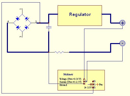
Description
| |
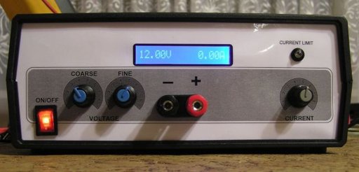
This
multimeter was designed to measure output voltage
and current in a PSU, where the current sense shunt
resistor is connected in series with load at the
negative voltage rail. It needs only one supply
voltage that can be acquired from main PSU. An additional
function of the multimeter is that it can control
(switch on and off) an electric fan used to cool
the main heatsink. The power threshold at which
the fan switches on can be adjusted using One Touch
Button Setup.
|
Schematic
| |
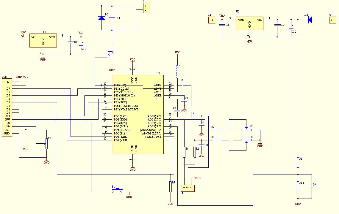
There
are elements on schematic and in the following table
marked as "Do Not Assemble". That elements
was needed in previous software edition. Current software
version doesn't , so you just don't add them. Maybe
in a future version of the multimeter there will be
a simpler PCB with simpler electronic diagram too.
|
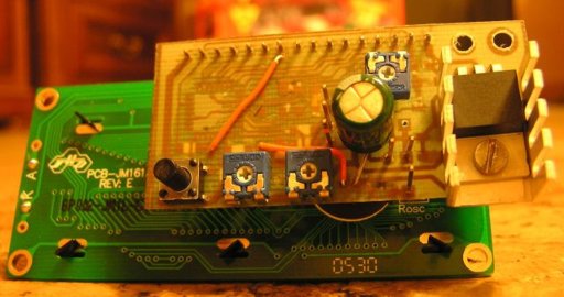
Installation
in Power Supply
| |
Mount multimeter to the power
supply according to the diagram below.
Connectors
and Regulation Elements
| ELEMENT |
ACTION |
| S1 |
Setup
button
When pushing this button the shunt resistor
value appears. If the resistor value is
known, repeat button pushing until correct
value reached. If resistor value is unknown
(e.g. self made resistor), short
PSU output by ammeter, set some current
by PSU current limit regulator and then,
push button, lead to equal current
indication on ammeter and multimeter.
After resistor value setup, button
must not be pressed for about 5 seconds.
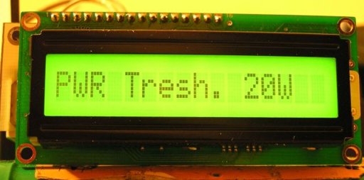
The next parameter to set up is fan switch-on
power threshold. It is not the real power loosed
on output transistor (transistors), because
multimeter has information on voltage
drop on transistor and driving current.
To avoid instability switch-off threshold
is automatically set to 20% less than
switch-on one. |
|
R9 |
Fine
voltage circuit regulation potentiometer.
To reduce ADC conversion errors like un-linearity,
gain factor etc. measuring range is divided
into two sub-ranges 0-10V and 10-30V (switch
threshold can be between 7-13V
depend on sourcing current and elements
tolerance).
To regulate fine sub-range connect
voltmeter to PSU output, set up voltage
at about 9V and turn R9 until voltmeter
and multimeter indications are equal. |
|
R10 |
Coarse
voltage circuit regulation potentiometer..
There is over-sampling applied in
multimeter software, so measuring resolution
is the same in fine and coarse circuit
and is 10mV. Because of the reason described
above multimeter has two measuring circuits.
To
regulate coarse sub-range connect
voltmeter to PSU output, set up voltage
at about 19V and turn R10 until voltmeter
and multimeter indication are equal.
(If you posses 4.5 digit voltmeter,
you could regulate at voltage 30V) |
|
R3 |
LCD contrast potentiometer. Turn that
potentiometer first, if nothing is visible
on LCD. |
|
J1 |
Fan connector.
Pin no. 1: Fan "+"
Pin no. 2: Fan "-" |
|
J2 |
+12V
If +12V DC is available in your PSU, connect
it to that pin. In that case you shouldn't
assemble +12V voltage regulator U2 on
PCB.
That solution is convenient for multimeter,
because eliminates U2 heating and permit
to connect fan and LCD with higher current
consumption.
If you haven't got +12V DC in your PSU,
left that pin unconnected. |
|
J3 |
+35V
Rectifier bridge voltage. See U2 element
you used data sheet to know about maximum
voltage it can work properly. On the other
hand the minimum voltage on that pin mustn't
drop bellow c.a. 9V, or 6.5V if low drop
type U2 and U3 voltage regulators were
used.
That pin should be connected even if +12V
DC is connected to J2 pin. Voltage from
that pin deliver information for fan switching. |
|
J4 |
Measuring signal connector.
Multimeter is suitable for voltage and
current measurement in PSU, where
current sense shunt resistor is connected
in series with load and is in negative
rail.
Pin no.1: voltage measurement U - connect
to "+" PSU output, best directly
to output terminal;
Pin no.2: current measurement I - connect
to "-" PSU output, best directly
to output terminal;
Pin no.3: ground - connect to shunt
resistor terminal opposite to that connected
to "-" PSU output. |
|
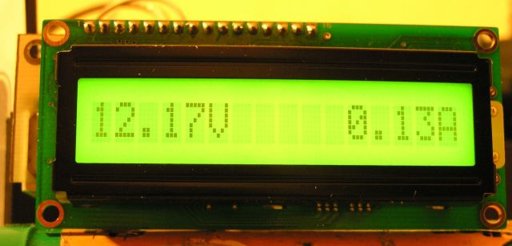
LCD |
LCD connector.
Multimeter works properly with LCD's 1x16
logical controlled as 2x8 (most of LCD's
available on the market).
Because of linear voltage regulators used
in multimeter, sourcing current is limited.
Main current consumption elements are
fan and LCD backlight, so:
- use LCD with LED backlight (typically
current consumption is less than 15mA);
- use low speed, low current fan. Additional
advantage of that solution will be silence. |
|
Programming
| |
Because
µC is in TQFP package, we can program
it after soldering all the elements on PCB.
It makes programming quite easy to perform.
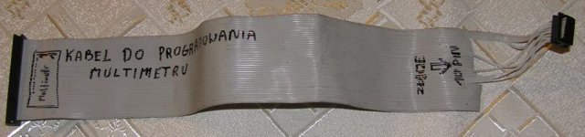
Programming signals are delivered through LCD
connector. To make the programming cable, you
can use old PC HDD cable. Picture of my programming
cable is shown below.
Remember,
that during programming multimetr circuit must
be supplied with +5V. Depending on your programmer,
supply voltage is provided either by programmer,
or from separate power supply unit.
Programming cable connection list
|
LCD Pin number |
LCD signal |
�C signal/Pin |
Prog signal |
| 1 |
GND |
GND |
GND |
| 2 |
VCC |
VCC |
VCC |
| 4 |
RS |
SCK / PB.5 |
SCK |
| 5 |
RW |
MISO / PB.4 |
MISO |
| 6 |
EN |
MOSI / PB.3 |
MOSI |
| 10 |
D3 |
RESET |
RESET |
After connecting µC
to prog, you should check, if µC is "visible"
for prog. When everything is fine, you can upload
code to µC. The code is available here.
It is assumed here, that µC is new and
works with its internal RC clock at 1MHz. If
not, set appropriate fusebits to archive above
mentioned conditions. In addition Brown-out
detector should be turned on by enabling BODEN
fuse. Recommended Brown-out Reset Threshold
Voltage is 4V.
The next thing to
do is to cross LCD soldering pads number 1 and
5. It is necessary to provide ground for LCD
RW signal. After all, connect LCD module with
the multi meter PCB. It is recommended to use
a detachable connector for further expandability
e.g. software upgrading.
|
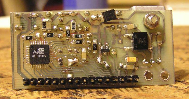
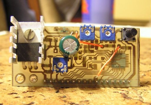
PCB
| |
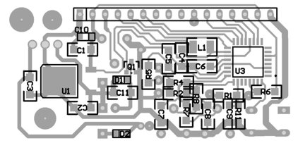
PCB Layout - Top
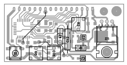
PCB Layout - Bottom
Picture of PCB is here.
There are two version of PCB - normal and mirrored.
I think, that anyone who makes PCBs will know,
which one should be used to produce right PCB.
After soldering all the parts on PCB:
* make two cross connection
on PCB (see "Layout - bottom side");
* short L1 pads;
* place U2 element (+12V voltage regulator) on
heatsink
* pay attention on right polarity D1 i D2 elements.
Wider side of silk screen layout, where part number
is placed, is CATHODE.
|
Pictures
Parts
List
| |
|
Element |
Value/Type |
Case |
Remarks |
R1 |
100k |
1206 |
|
R2 |
100k |
1206 |
|
R3 |
10k |
|
Potentiometer |
R4 |
30k |
1206 |
|
R5 |
10k |
1206 |
|
R6 |
10k |
1206 |
|
R7 |
7k5 |
1206 |
|
R8 |
7k5 |
1206 |
|
R9 |
500R |
|
Potentiometer |
R10 |
500R |
|
Potentiometer |
R11 |
5k1 |
1206 |
|
C1 |
100n |
1206 |
|
C2 |
100n |
1206 |
|
C3 |
100n |
1206 |
|
C4 |
100n |
1206 |
Do Not Assemble |
C5 |
100n |
1206 |
Do Not Assemble
|
C6 |
100n |
1206 |
Do Not Assemble
|
C7 |
100n |
1206 |
Do Not Assemble
|
C8 |
100n |
1206 |
Do Not Assemble
|
C9 |
100n |
1206 |
Do Not Assemble
|
C10 |
22u/6V |
SMD A |
|
C11 |
10n |
1206 |
Optional element
- protect Q1 against voltage peek after
switch off fan. Most of the computer type
fans which I tested didn't produce voltage
peeks dangerous for Q1 |
C12 |
10u/50V |
|
|
L1 |
47u |
1210 |
Do Not Assemble
- cross PCB pads |
D1 |
DIODE |
SMD A |
Optional element
- protect Q1 against voltage peek after
switch off fan. Most of the computer type
fans which I tested didn't produce voltage
peeks dangerous for Q1 |
D2 |
DIODE |
SMD A |
e.g. SK310A |
U1 |
7805 |
TO-252 |
Voltage regulator
+5V, e.g. LM7805 |
U2 |
7812 |
TO220 |
Voltage regulator
+12V, e.g. LM7812 |
U3 |
ATMEGA8 |
TQFP32 |
|
LCD |
GOLDPIN |
1x16 |
|
J1 |
GOLDPIN |
1x2 |
FAN_CON - fan
connector |
J2 |
GOLDPIN |
1x1 |
+12V_CON - optional
+12V supply connector |
J3 |
GOLDPIN |
1x1 |
+35V_CON
- main supply connector |
J4 |
GOLDPIN |
1x3 |
ground and measured
signals |
S1 |
SWITCH |
|
|
Q1 |
MOSFET
N |
SOT-23 |
e.g. BSS-138 (fan
current lees than 200mA) |
|
Warnings
| |
This circuit itself doesn't work off the mains and there are not
220 VAC present, but PSU does.
Voltages above 50 V are DANGEROUS and could
even be LETHAL.
In order to avoid accidents that could be fatal
to you or members of your family please observe
the following rules:
* DO NOT work if you are tired
or in a hurry, double check every thing before
connecting your circuit to the mains and be
ready to disconnect it if something looks wrong.
* DO NOT touch any part of the circuit when
it is under power.
* DO NOT leave mains leads exposed. All mains
leads should be well insulated.
* DO NOT change the fuses with others of higher
rating or replace them with wire or aluminium
foil.
* DO NOT work with wet hands.
* If you are wearing a chain, necklace or anything
that may be hanging and touch an exposed part
of the circuit
* ALWAYS use a proper mains lead with the correct
plug and earth your circuit properly.
* If the case of your project is made of metal
make sure that it is properly earthen.
* If it is possible use a mains transformer
with a 1:1 ratio to isolate your circuit from
the mains.
* When you are testing a circuit that works
off the mains wear shoes with rubber soles,
stand on dry non conductive floor and keep one
hand in your pocket or behind your back.
If you take all the above precautions
you are reducing the risks you are taking to
a minimum and this way you are protecting yourself
and those around you.
A carefully built and well insulated device
does not constitute any danger for its user.
|
Volt Ampere Meter Kit
| |
You can purchase a complete premium quality Volt Ampere Meter Kit at Electronics-DIY store. Please see the link for more details.
|
Related Links
|
|
|
| |
Accurate LC Meter
Build your own Accurate LC Meter (Capacitance Inductance Meter) and start making your own coils and inductors. This LC Meter allows to measure incredibly small inductances making it perfect tool for making all types of RF coils and inductors. LC Meter can measure inductances starting from 10nH - 1000nH, 1uH - 1000uH, 1mH - 100mH and capacitances from 0.1pF up to 900nF. The circuit includes an auto ranging as well as reset switch and produces very accurate and stable readings. |
|
PIC Volt Ampere Meter
Volt Ampere Meter measures voltage of 0-70V or 0-500V with 100mV resolution and current consumption 0-10A or more with 10mA resolution. The meter is a perfect addition to any power supply, battery chargers and other electronic projects where voltage and current must be monitored. The meter uses PIC16F876A microcontroller with 16x2 backlighted LCD. |
|
|
|
60MHz Frequency Meter / Counter
Frequency Meter / Counter measures frequency from 10Hz to 60MHz with 10Hz resolution. It is a very useful bench test equipment for testing and finding out the frequency of various devices with unknown frequency such as oscillators, radio receivers, transmitters, function generators, crystals, etc. |
|
1Hz - 2MHz XR2206 Function Generator
1Hz - 2MHz XR2206 Function Generator produces high quality sine, square and triangle waveforms of high-stability and accuracy. The output waveforms can be both amplitude and frequency modulated. Output of 1Hz - 2MHz XR2206 Function Generator can be connected directly to 60MHz Counter for setting precise frequency output. |
|
|
|
BA1404 HI-FI Stereo FM Transmitter
Be "On Air" with your own radio station! BA1404 HI-FI Stereo FM Transmitter broadcasts high quality stereo signal in 88MHz - 108MHz FM band. It can be connected to any type of stereo audio source such as iPod, Computer, Laptop, CD Player, Walkman, Television, Satellite Receiver, Tape Deck or other stereo system to transmit stereo sound with excellent clarity throughout your home, office, yard or camp ground. |
|
USB IO Board
USB IO Board is a tiny spectacular little development board / parallel port replacement featuring PIC18F2455/PIC18F2550 microcontroller. USB IO Board is compatible with Windows / Mac OSX / Linux computers. When attached to Windows IO board will show up as RS232 COM port. You can control 16 individual microcontroller I/O pins by sending simple serial commands. USB IO Board is self-powered by USB port and can provide up to 500mA for electronic projects. USB IO Board is breadboard compatible. |
|
|
|
|
ESR Meter / Capacitance / Inductance / Transistor Tester Kit
ESR Meter kit is an amazing multimeter that measures ESR values, capacitance (100pF - 20,000uF), inductance, resistance (0.1 Ohm - 20 MOhm), tests many different types of transistors such as NPN, PNP, FETs, MOSFETs, Thyristors, SCRs, Triacs and many types of diodes. It also analyzes transistor's characteristics such as voltage and gain. It is an irreplaceable tool for troubleshooting and repairing electronic equipment by determining performance and health of electrolytic capacitors. Unlike other ESR Meters that only measure ESR value this one measures capacitor's ESR value as well as its capacitance all at the same time. |
|
Audiophile Headphone Amplifier Kit
Audiophile headphone amplifier kit includes high quality audio grade components such as Burr Brown OPA2134 opamp, ALPS volume control potentiometer, Ti TLE2426 rail splitter, Ultra-Low ESR 220uF/25V Panasonic FM filtering capacitors, High quality WIMA input and decoupling capacitors and Vishay Dale resistors. 8-DIP machined IC socket allows to swap OPA2134 with many other dual opamp chips such as OPA2132, OPA2227, OPA2228, dual OPA132, OPA627, etc. Headphone amplifier is small enough to fit in Altoids tin box, and thanks to low power consumption may be supplied from a single 9V battery. |
|
|
|
|
|
Arduino Prototype Kit
Arduino Prototype is a spectacular development board fully compatible with Arduino Pro. It's breadboard compatible so it can be plugged into a breadboard for quick prototyping, and it has VCC & GND power pins available on both sides of PCB. It's small, power efficient, yet customizable through onboard 2 x 7 perfboard that can be used for connecting various sensors and connectors. Arduino Prototype uses all standard through-hole components for easy construction, two of which are hidden underneath IC socket. Board features 28-PIN DIP IC socket, user replaceable ATmega328 microcontroller flashed with Arduino bootloader, 16MHz crystal resonator and a reset switch. It has 14 digital input/output pins (0-13) of which 6 can be used as PWM outputs and 6 analog inputs (A0-A5). Arduino sketches are uploaded through any USB-Serial adapter connected to 6-PIN ICSP female header. Board is supplied by 2-5V voltage and may be powered by a battery such as Lithium Ion cell, two AA cells, external power supply or USB power adapter. |
|
200m 4-Channel 433MHz Wireless RF Remote Control
Having the ability to control various appliances inside or outside of your house wirelessly is a huge convenience, and can make your life much easier and fun. RF remote control provides long range of up to 200m / 650ft and can find many uses for controlling different devices, and it works even through the walls. You can control lights, fans, AC system, computer, printer, amplifier, robots, garage door, security systems, motor-driven curtains, motorized window blinds, door locks, sprinklers, motorized projection screens and anything else you can think of. |
|
|
|
|
|