|
| BA1404 Stereo FM Transmitter Components:
|
BA1404 IC
38KHz Crystal
L1 - 3.5 Turns Variable Coil
1x PCB
1x 38KHz Crystal Oscillator
1x DIP-18 IC Socket
1x 3.5T Variable Precision RF Coil
1x 10uH Inductor
4x 10uF/50V Gold Audio Capacitors
4x 1nF Ceramic Capacitors
2x 1nF Mylar Capacitors
1x 220pF Ceramic Capacitor
5x 10pF Ceramic Capacitors
2x 47K 1% Metal Film Resistors
2x 27K 1% Metal Film Resistors
1x 150K 1% Metal Film Resistor
1x 5.6K 1% Metal Film Resistor
1x 270 1% Metal Film Resistor |
|
|
|
| Technical
Specifications:
|
Supply
Voltage: 1.5 - 3V
Dimensions: 49 mm x 32 mm x 10 mm (W x H x D) |
|
|
|
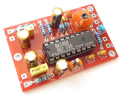
BA1404 HI-FI Stereo FM Transmitter
BA1404 HI-FI Stereo FM Transmitter
| |
Whether
you want to create your own radio station, transmit
the music around the house, or simply create a
wireless link between your iPod and a receiver
in your car, this transmitter will let you do
these things easily. With BA1404 HI-FI Stereo
transmitter you will be able to transmit MP3 music
from your iPod, computer, discman, walkman, TV
/ SAT receiver, and many other audio sources.
The above FM transmitter design is a result of
many hours of testing and tweaking. The goal was
simple; to test many existing BA1404 transmitter
designs, compare their performance, identify weaknesses
and come up with a new BA1404 transmitter design
that improves sound quality, has very good frequency
stability, maximizes transmitter's range, and
is fairly simple for everyone to build. We are
happy to announce that this goal and expectations
have been met and even exceeded.
The transmitter can work from a single 1.5V cell
battery and provide excellent crystal clear stereo
sound. It can also be supplied from two 1.5V battery
cells to provide the maximum range. |
Secrets Behind Sound Quality and Frequency Stability
| |
One of the
qualities of BA1404 FM transmitter is excellent
frequency stability. This is mainly due to a use
of high quality 3.5 turn variable coil. Tunable
RF coils are ideal for precise frequency tuning
because their magnet wire is halfway embedded within
the plastic, which minimizes frequency drifts. Regular
air coils are not preferred for professional broadcasting
because the coil expands and contracts with temperature
changes. That's the very reason why variable coil
was chosen as a substitution for an air coil and
a variable capacitor.

Another quality of the presented BA1404 transmitter is a crystal clear stereo sound and improved sound separation. There are several factors that account for improved sound quality and a separation. First reason is the use of 38 KHz crystal which provides rock solid frequency for stereo encoder. Another reason is the use of two 1nF decoupling capacitors one for BA1404 chip and another for 3.5 variable coil. These capacitors have to be as close as possible to a BA1404 chip and a variable coil because this will GREATLY improve the sound quality, sound separation and even frequency stability as well. What they do is filter out the noise in the incoming DC voltage. If the noise enters BA1404 chip stereo generator will include it in a transmitted sound affecting both the sound and multiplex signal that is responsible for generation of the clear stereo signal. If that noise enters it will also be included in a generation of subcarrier frequency affecting the frequency stability. Most people are not aware of how important this is and might place them in a wrong location, away from the target components which provides no use, or worse decide not to use these capacitors at all.
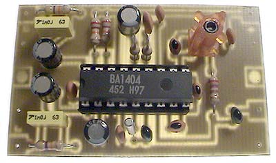
Another factor that is extremely important and which improves overall quality of the whole BA1404 transmitter including frequency stability, sound quality and sound separation is the use of the ground plane on the transmitter’s PCB. It is recommended that ground plane should always be used in circuits that deal with higher frequencies.
|
Antenna
| |
For optimum transmission range the length of the antenna should be 1/4 or 1/2 of the wave length of the transmitted frequency. Use this simplified formula to determine the antenna length for 1/4 wave length antenna type:
(30000 / Transmitted Frequency) / 4 = Antenna Length (in cm)
Example:
(30000 / 88MHz) / 4 = 85cm Antenna
(30000 / 108MHz) / 4 = 70cm Antenna
|
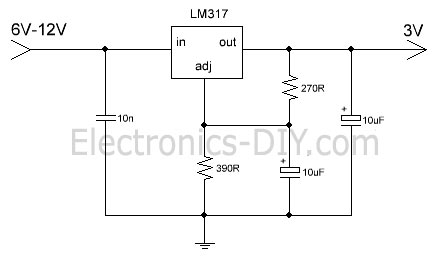
Optional 12V to 3V Voltage Regulator
| |
If you need to supply BA1404 FM Transmitter from 12V this simple circuit will do the job. It converts 12V voltage to 3V suitable for BA1404 chip using LM317 voltage regulator. 270 and 390 Ohm resistor determine the output voltage.
 . .
|
Frequently Asked Questions
| |
This
is list of answers to questions that I have
received through an e-mail so far. If you should
have any other questions please don't hesitate
to e-mail them to me.
What is the range of BA1404 Stereo FM
Transmitter?
Range of the transmitter depends on many factors.
a) Length and type of the antenna (copper wire or pipe will radiate radio waves
better than aluminum)
b) Supplied voltage (3V Max power output)
c) Weather conditions (clear skies & no
humid, greater distance)
d) Elevation above the ground (the higher the
better)
e) Line of sight (no buildings or trees, greater
distance)
f) Whether external amplifier is used
I want to use the BA1404 Transmitter
in my car for my iPod. What can i do to reduce
an output power?
Supply the transmitter with just 1.5V voltage
supply (single AA battery cell) and minimize
the length of the antenna.
Can I replace a variable coil with regular air
coil and variable capacitor / trimmer?
This is possible but keep in mind that frequency
stability will be decreased with temperature
drifts.
How can frequency of the BA1404 transmitter
be controlled with a varicap diode?
Check this section for some theory and examples
on how
to use tuning diodes.
I would like to be able to transmit
the music to greater distances. Can you provide
any suggestions on how to modify the circuit?
You can connect an external
amplifier based on the common 2N3866 / 2N4427
RF transistors. Please keep in mind that it
is illegal to operate higher power transmitters
in most of the countries without the proper
license.
|
500mW FM / VHF Transmitter Amplifier / Booster
| |
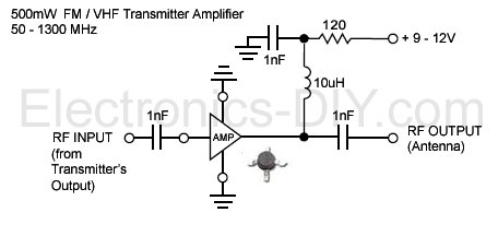
You can easily boost output power and range of BA1404 FM Transmitter by adding this simple high performance 500mW amplifier / booster. The amplifier chip is an integrated circuit containing multiple transistor stages and all other parts conveniently within a single small package. Boosting BA1404 FM transmitter's power has never been easier and the output signal can also directly drive 2N4427 or 2N3886 transistors for 1W or 5W of RF output power.
|
Where to get the Parts
| |
If you are building above BA1404 Stereo FM Transmitter and have trouble
finding some of the components like BA1404 IC,
38KHz crystals and 3.5 turn high precision variable
coils we are distributing them
in our Electronic-DIY
Store.
For those who are interested in a complete BA1404 Transmitter Kit version that comes with a PCB (pictured below) or for 500mW FM / VHF Transmitter Amplifier / Booster please see Electronic
Kits section for more details.
|
Related Links
|
|
|
| |
Accurate LC Meter
Build your own Accurate LC Meter (Capacitance Inductance Meter) and start making your own coils and inductors. This LC Meter allows to measure incredibly small inductances making it perfect tool for making all types of RF coils and inductors. LC Meter can measure inductances starting from 10nH - 1000nH, 1uH - 1000uH, 1mH - 100mH and capacitances from 0.1pF up to 900nF. The circuit includes an auto ranging as well as reset switch and produces very accurate and stable readings. |
|
PIC Volt Ampere Meter
Volt Ampere Meter measures voltage of 0-70V or 0-500V with 100mV resolution and current consumption 0-10A or more with 10mA resolution. The meter is a perfect addition to any power supply, battery chargers and other electronic projects where voltage and current must be monitored. The meter uses PIC16F876A microcontroller with 16x2 backlighted LCD. |
|
|
|
60MHz Frequency Meter / Counter
Frequency Meter / Counter measures frequency from 10Hz to 60MHz with 10Hz resolution. It is a very useful bench test equipment for testing and finding out the frequency of various devices with unknown frequency such as oscillators, radio receivers, transmitters, function generators, crystals, etc. |
|
1Hz - 2MHz XR2206 Function Generator
1Hz - 2MHz XR2206 Function Generator produces high quality sine, square and triangle waveforms of high-stability and accuracy. The output waveforms can be both amplitude and frequency modulated. Output of 1Hz - 2MHz XR2206 Function Generator can be connected directly to 60MHz Counter for setting precise frequency output. |
|
|
|
BA1404 HI-FI Stereo FM Transmitter
Be "On Air" with your own radio station! BA1404 HI-FI Stereo FM Transmitter broadcasts high quality stereo signal in 88MHz - 108MHz FM band. It can be connected to any type of stereo audio source such as iPod, Computer, Laptop, CD Player, Walkman, Television, Satellite Receiver, Tape Deck or other stereo system to transmit stereo sound with excellent clarity throughout your home, office, yard or camp ground. |
|
USB IO Board
USB IO Board is a tiny spectacular little development board / parallel port replacement featuring PIC18F2455/PIC18F2550 microcontroller. USB IO Board is compatible with Windows / Mac OSX / Linux computers. When attached to Windows IO board will show up as RS232 COM port. You can control 16 individual microcontroller I/O pins by sending simple serial commands. USB IO Board is self-powered by USB port and can provide up to 500mA for electronic projects. USB IO Board is breadboard compatible. |
|
|
|
|
ESR Meter / Capacitance / Inductance / Transistor Tester Kit
ESR Meter kit is an amazing multimeter that measures ESR values, capacitance (100pF - 20,000uF), inductance, resistance (0.1 Ohm - 20 MOhm), tests many different types of transistors such as NPN, PNP, FETs, MOSFETs, Thyristors, SCRs, Triacs and many types of diodes. It also analyzes transistor's characteristics such as voltage and gain. It is an irreplaceable tool for troubleshooting and repairing electronic equipment by determining performance and health of electrolytic capacitors. Unlike other ESR Meters that only measure ESR value this one measures capacitor's ESR value as well as its capacitance all at the same time. |
|
Audiophile Headphone Amplifier Kit
Audiophile headphone amplifier kit includes high quality audio grade components such as Burr Brown OPA2134 opamp, ALPS volume control potentiometer, Ti TLE2426 rail splitter, Ultra-Low ESR 220uF/25V Panasonic FM filtering capacitors, High quality WIMA input and decoupling capacitors and Vishay Dale resistors. 8-DIP machined IC socket allows to swap OPA2134 with many other dual opamp chips such as OPA2132, OPA2227, OPA2228, dual OPA132, OPA627, etc. Headphone amplifier is small enough to fit in Altoids tin box, and thanks to low power consumption may be supplied from a single 9V battery. |
|
|
|
|
|
Arduino Prototype Kit
Arduino Prototype is a spectacular development board fully compatible with Arduino Pro. It's breadboard compatible so it can be plugged into a breadboard for quick prototyping, and it has VCC & GND power pins available on both sides of PCB. It's small, power efficient, yet customizable through onboard 2 x 7 perfboard that can be used for connecting various sensors and connectors. Arduino Prototype uses all standard through-hole components for easy construction, two of which are hidden underneath IC socket. Board features 28-PIN DIP IC socket, user replaceable ATmega328 microcontroller flashed with Arduino bootloader, 16MHz crystal resonator and a reset switch. It has 14 digital input/output pins (0-13) of which 6 can be used as PWM outputs and 6 analog inputs (A0-A5). Arduino sketches are uploaded through any USB-Serial adapter connected to 6-PIN ICSP female header. Board is supplied by 2-5V voltage and may be powered by a battery such as Lithium Ion cell, two AA cells, external power supply or USB power adapter. |
|
200m 4-Channel 433MHz Wireless RF Remote Control
Having the ability to control various appliances inside or outside of your house wirelessly is a huge convenience, and can make your life much easier and fun. RF remote control provides long range of up to 200m / 650ft and can find many uses for controlling different devices, and it works even through the walls. You can control lights, fans, AC system, computer, printer, amplifier, robots, garage door, security systems, motor-driven curtains, motorized window blinds, door locks, sprinklers, motorized projection screens and anything else you can think of. |
|
|
|