This section summarises the key features and enhancements of the FT232RL IC device.
Integrated Clock Circuit - Previous generations of FTDI's USB UART devices required an external crystal or ceramic resonator. The clock circuit has now been integrated onto the device meaning that no crystal or ceramic resonator is required. However, if preferred, an external 12MHz crystal can be used as the clock source.
Integrated EEPROM - Previous generations of FTDI's USB UART devices required an external EEPROM if the device were to use USB Vendor ID (VID), Product ID (PID), serial number and product description strings other than the default values in the device itself. This external EEPROM has now been integrated onto the FT232R chip meaning that all designs have the option to change the product description strings. A user area of the internal EEPROM is available for storing additional data. The internal EEPROM is programmable in circuit, over USB without any additional voltage requirement. Preprogrammed EEPROM - The FT232R is supplied with its internal EEPROM pre-programmed with a serial number which is unique to each individual device. This, in most cases, will remove the need to program the device EEPROM.
Integrated USB Resistors - Previous generations of FTDI's USB UART devices required two external series resistors on the USBDP and USBDM lines, and a 1.5 kΩ pull up resistor on USBDP. These three resistors have now been integrated onto the device.
Integrated AVCC Filtering - Previous generations of FTDI's USB UART devices had a separate AVCC pin – the supply to the internal PLL. This pin required an external R-C filter. The separate AVCC pin is now connected internally to VCC, and the filter has now been integrated onto the chip.
Less External Components - Integration of the crystal, EEPROM, USB resistors, and AVCC filter will substantially reduce the bill of materials cost for USB interface designs using the FT232R compared to its FT232BM predecessor.
Configurable CBUS I/O Pin Options - There are now 5 configurable Control Bus (CBUS) lines. Options are TXDEN - transmit enable for RS485 designs, PWREN# - Power control for high power, bus powered designs, TXLED# - for pulsing an LED upon transmission of data, RXLED# - for pulsing an LED upon receiving data, TX&RXLED# - which will pulse an LED upon transmission OR reception of data, SLEEP# - indicates that the device going into USB suspend mode, CLK48 / CLK24 / CLK12 / CLK6 - 48MHz, 24MHz,12MHz, and 6MHz clock output signal options. There is also the option to bring out bit bang mode read and write strobes (see below). The CBUS lines can be configured with any one of these output options by setting bits in the internal EEPROM. The device is supplied with the most commonly used pin definitions pre-programmed - see Section 9 for details.
Enhanced Asynchronous Bit Bang Mode with RD# and WR# Strobes - The FT232R supports FTDI's BM chip bit bang mode. In bit bang mode, the eight UART lines can be switched from the regular interface mode to an 8-bit general purpose I/O port. Data packets can be sent to the device and they will be sequentially sent to the interface at a rate controlled by an internal timer (equivalent to the baud rate prescaler). With the FT232R device this mode has been enhanced so that the internal RD# and WR# strobes are now brought out of the device which can be used to allow external logic to be clocked by accesses to the bit bang I/O bus. This option will be described more fully in a separate application note.
Synchronous Bit Bang Mode - Synchronous bit bang mode differs from asynchronous bit bang mode in that the interface pins are only read when the device is written to. Thus making it easier for the controlling program to measure the response to an output stimulus as the data returned is synchronous to the output data. The feature was previously seen in FTDI's FT2232C device. This option will be described more fully in a separate application note. CBUS Bit Bang Mode - This mode allows four of the CBUS pins to be individually configured as GPIO pins, similar to Asynchronous bit bang mode. It is possible to use this mode while the UART interface is being used, thus providing up to four general purpose I/O pins which are available during normal operation. An application note describing this feature is available separately from www.ftdichip.com. Lower Supply Voltage - Previous generations of the chip required 5V supply on the VCC pin. The FT232R will work with a VCC supply in the range 3.5V to 5.25V. Bus powered designs would still take their supply from the 5V on the USB bus, but for self powered designs where only 3.5V is available and there is no 5V supply there is no longer any need for an additional external regulator.
Integrated Level Converter on UART Interface and Control Signals - VCCIO pin supply can be from 1.8V to 5V. Connecting the VCCIO pin to 1.8V, 2.8V, or 3.3V allows the device to directly interface to 1.8V, 2.8V or 3.3V and other logic families without the need for external level converter I.C. devices. 5V / 3.3V / 2.8V / 1.8V Logic Interface - The FT232R provides true CMOS Drive Outputs and TTL level Inputs.
Integrated Power-On-Reset (POR) Circuit- The device incorporates an internal POR function. A RESET# pin is available in order to allow external logic to reset the FT232R where required. However, for many applications the RESET# pin can be left unconnected, or pulled up to VCCIO.
Lower Operating and Suspend Current - The device operating supply current has been further reduced to 15mA, and the suspend current has been reduced to around 70μA. This allows greater margin for peripheral designs to meet the USB suspend current limit of 500μA.
Low USB Bandwidth Consumption - The operation of the USB interface to the FT232R has been designed to use as little as possible of the total USB bandwidth available from the USB host controller.
Low USB Bandwidth Consumption - The operation of the USB interface to the FT232R has been designed to use as little as possible of the total USB bandwidth available from the USB host controller.
Power Management Control for USB Bus Powered, High Current Designs - The PWREN# signal can be used to directly drive a transistor or P-Channel MOSFET in applications where power switching of external circuitry is required. An option in the internal EEPROM makes the device gently pull down on its UART interface lines when the power is shut off (PWREN# is high). In this mode any residual voltage on external circuitry is bled to GND when power is removed, thus ensuring that external circuitry controlled by PWREN# resets reliably when power is restored.
UART Pin Signal Inversion - The sense of each of the eight UART signals can be individually inverted by setting options in the internal EEPROM. Thus, CTS# (active low) can be changed to CTS (active high), or TXD can be changed to TXD#.
FTDIChip-ID™ - Each FT232R is assigned a unique number which is burnt into the device at manufacture. This ID number cannot be reprogrammed by product manufacturers or end-users. This allows the possibility of using FT232R based dongles for software licensing. Further to this, a renewable license scheme can be implemented based on the FTDIChip-ID™ number when encrypted with other information. This encrypted number can be stored in the user area of the FT232R internal EEPROM, and can be decrypted, then compared with the protected FTDIChip-ID™ to verify that a license is valid. Web based applications can be used to maintain product licensing this way.
Performance - The reduced operating current and improved on-chip VCC decoupling significantly improves the ease of PCB design requirements in order to meet FCC, CE and other EMI related specifications.
Programmable Receive Buffer Timeout - The receive buffer timeout is used to flush remaining data from the receive buffer. This time defaults to 16ms, but is programmable over USB in 1ms increments from 1ms to 255ms, thus allowing the device to be optimised for protocols that require fast response times from short data packets.
Rates - The FT232R supports all standard baud rates and non-standard baud rates from 300 Baud up to 3 Megabaud. Achievable non-standard baud rates are calculated as follows -Baud Rate = 3000000 / (n + x) where „n‟ can be any integer between 2 and 16,384 (= 214 ) and „x’ can be a sub-integer of the value 0, 0.125, 0.25, 0.375, 0.5, 0.625, 0.75, or 0.875. When n = 1, x = 0, i.e. baud rate divisors with values between 1 and 2 are not possible. This gives achievable baud rates in the range 183.1 baud to 3,000,000 baud. When a non-standard baud rate is required simply pass the required baud rate value to the driver as normal, and the FTDI driver will calculate the required divisor, and set the baud rate. See FTDI application note AN232B-05 for more details.
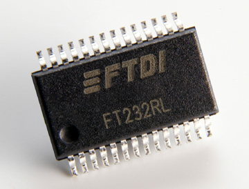
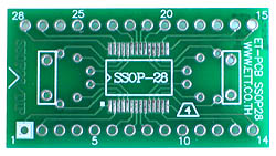
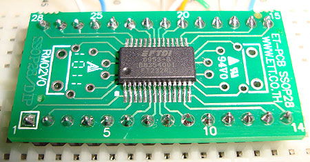
Temperature Range - The FT232R operates over an extended temperature range of -40º to +85º C thus allowing the device to be used in automotive and industrial applications. Package Options - The FT232R is available in two packages - a compact 28 pin SSOP ( FT232RL) and an ultra-compact 5mm x 5mm pinless QFN-32 package ( FT232RQ). Both packages are lead ( Pb ) free, and use a „green‟ compound. Both packages are fully compliant with European Union directive 2002/95/EC.