| USB IO Board Component List:
|
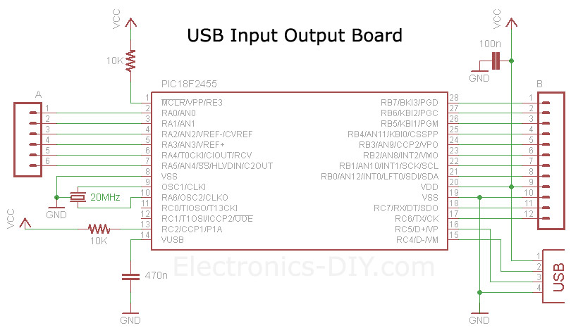
1x PIC18F2455 / PIC18F2550 Programmed Microcontroller (MCU)
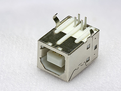
1x USB Type B Connector
1x 20MHz Crystal Resonator
2x 10K Resistor (brown black orange gold)
1x 470 Resistor (yellow purple brown gold)
1x 470nF Ceramic Capacitor
1x 100nF Ceramic Capacitor |
|
|
|
|
| Technical
Specifications:
|
Voltage Supply: 5V (USB powered)
Current Consumption: 5mA
I/O PINs: 16
|
|
|
|
About PIC18F2455 / PIC18F2550 USB IO Board
| |
USB Input / Output Board is a spectacular little development board / parallel port replacement featuring PIC18F2455 / PIC18F2550 microcontroller. USB IO Board is compatibile with Windows / Mac OSX / Linux computers. When attached to Windows IO board will show up as RS232 COM port. You can control 16 individual microcontroller I/O pins by sending simple serial commands. USB Input / Output Board is self-powered by USB port and can provide up to 500mA for electronic projects. USB IO Board is breadboard compatible. Simply solder included 12-PIN & 8-PIN headers on the bottom side of the PCB and the board can be plugged into a breadboard for quick prototyping.
These are examples of what can be built using USB IO Board
USB Relay Controller (turn ON/OFF lights or appliances in the house)
Control LEDs, toys, electronic gadgets, wireless control, etc.
USB LCD Controller
USB Volt / Ampere / Wattage Meter
USB CNC Controller
USB Data Logger
USB Temperature Meter / Logger
USB Thermostat Controller
USB Humidity Meter / Logger
USB Stepper Motor Controller
USB RC Servo Controller
USB Countdown Timer with Relay
|
USB IO Board Schematic
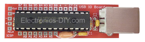
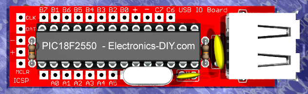
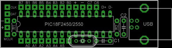
USB IO Board PCB Layout
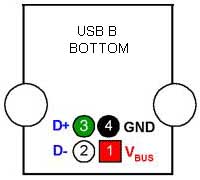
USB Connector
Quick Start
| |
1) Download USB IO Board drivers and unzip it.
2) Connect USB IO Board to a computer using standard USB cable.
3) Windows will ask you if you want to install a driver. Point it to drivers you unzipped.
Windows 2000 / XP
Under Windows 2000 or XP you will be prompted twice to install two drivers.
On the first prompt please browse and point to MCHPUSB driver folder.
On the second prompt please browse and point to USB CDC driver folder.
Windows 7 / VISTA
Under Windows 7 or VISTA you might be only prompted once to install
USB CDC driver if MCHPUSB driver is already installed.
4) After the drivers are installed go to the Device Manager
(right click on My Computer and click Properties->Hardware->Device Manager),
and look under the Ports (COM & LPT) section, and you should see a new serial port there. Note the COM port number.
5) Open up your favorite serial emulator; the really awful HyperTerminal that
comes with Windows, or my personal favorite USB IO Board Controller which
can be downloaded here.
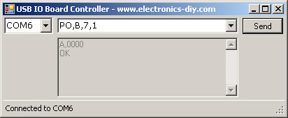
6) After launching USB IO Board Controller select the COM port from the drop-down
list to connect to the board, type 'V' in the input box and hit
Enter or click on 'Send' button. You should get back a firmware version number from PIC18F2455 / PIC18F2550 chip.
This proves that USB IO Board is working properly. Now you are ready to learn about the commands
that can be used to control USB IO Board. |
USB IO Board Controller
| |
USB IO Board can be controlled with just about any serial port emulation program such as Hyper Terminal that comes with every Windows OS. The problem with Hyper Terminal is that you can't see the commands as you type them and that could be very annoying. With Hyper Terminal you also have to go through the wizard for setting up a serial port connection, and if the COM port changes you pretty much have to do it over and over again.
Luckily we have released our own little application called USB IO Board Controller that is so much easier and fun to use than Hyper Terminal. It only takes 25KB of space so it's very lightweight. USB IO Board Controller will also show you COM port of USB IO Board so that will save you the trip (and time) to Device Manager to find out USB IO Board COM port number.
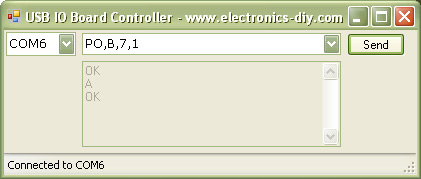
To use
USB IO Board Controller select the COM port from the drop down list, type the command and hit "Enter" key (or click on Send button). Each command returns "OK" message to acknowlege that the command was received and processed successfully.
Download USB IO Board Controller (Win 2K, XP, VISTA, Win7)
Note: If you try to execute USB IO Board Controller and it doesn't work you will need to download and install
Microsoft .NET Framework 3.5
Below you will find USB IO Board Controller source code written in C# and Visual Basic .NET using free Visual Studio 2008 Express IDE software. Use it as a foundation to get started on any projects of your choice. The code demonstrates how to list COM ports, connect to COM port, send commands and receive data from USB IO Board.
Download free copy of Visual C# 2008 Express or Visual Basic 2008 Express
| USB IO Board Controller - C# Source Code |
//=============================================================================
// USB IO Board Controller v2.0
// Copyright www.Electronics-DIY.com � 2002-2012. All Rights Reserved.
// THIS SOURCE CODE CAN ONLY BE USED FOR PERSONAL USE
// DO NOT REPRODUCE WITHOUT PERMISSION
//=============================================================================
// Compiled with free Visual C# 2008 Express
// http://www.microsoft.com/visualstudio/en-us/products/2008-editions/express
//=============================================================================
using System;
using System.Windows.Forms;
using System.IO.Ports;
namespace USB_IO_Board_Controller
{
public partial class Form1 : Form
{
public SerialPort Port = new SerialPort("COM1", 57600, Parity.None, 8, StopBits.One);
public Form1()
{
InitializeComponent();
}
private void Form1_Load(object sender, EventArgs e)
{
ListCOMPorts();
}
// List COM Ports
private void ListCOMPorts()
{
foreach (string s in SerialPort.GetPortNames())
{
cboCOMPorts.Items.Add(s);
}
cboCOMPorts.Sorted = true;
}
// Connect to COM Port
private void cboCOMPorts_SelectedIndexChanged(object sender, EventArgs e)
{
try
{
Port.PortName = cboCOMPorts.Text;
if (!Port.IsOpen)
{
StatusBar.Text = "Connected to " + Port.PortName;
Port.Open();
}
}
catch (Exception ex)
{
MessageBox.Show(ex.Message);
}
}
// Send Command to USB IO Board
private void btnSend_Click(object sender, EventArgs e)
{
if (Port.IsOpen)
{
//Port.Write("C,0,0,0,0" + '\r'); //Example: Configure all ports as outputs
Port.Write(cboCommandInput.Text + '\r');
System.Threading.Thread.Sleep(100); //ms
ReceiveData();
}
else
{
StatusBar.Text = "Select COM port";
}
}
// Receive Data from USB IO Board
private void ReceiveData()
{
string output = null;
byte[] Buffer = new byte[Port.BytesToRead];
Port.Read(Buffer, 0, Port.BytesToRead);
for (int i = 0; i <= Buffer.Length - 1; i++)
{
output += Microsoft.VisualBasic.Strings.Chr(Buffer[i]);
}
txtOutput.Text = output + txtOutput.Text;
}
}
}
Download USB IO Board Controller Project Files |
USB IO Board Controller - VB.NET Source Code |
'=============================================================================
' USB IO Board Controller v2.0
' Copyright www.Electronics-DIY.com � 2002-2012. All Rights Reserved.
' THIS SOURCE CODE CAN ONLY BE USED FOR PERSONAL USE
' DO NOT REPRODUCE WITHOUT PERMISSION
'=============================================================================
' Compiled with free Visual Basic 2008 Express
' http://www.microsoft.com/visualstudio/en-us/products/2008-editions/express
'=============================================================================
Imports System.IO.Ports
Public Class Form1
Public WithEvents Port As SerialPort = New SerialPort("COM1", 57600, Parity.None, 8, StopBits.One)
Private Sub Form1_Load(ByVal sender As System.Object, ByVal e As System.EventArgs) Handles MyBase.Load
ListCOMPorts()
End Sub
' List COM Ports
Private Sub ListCOMPorts()
For Each s As String In SerialPort.GetPortNames()
cboCOMPorts.Items.Add(s)
Next
cboCOMPorts.Sorted = True
End Sub
' Connect to COM Port
Private Sub cbo_SelectedIndexChanged(ByVal sender As System.Object, ByVal e As System.EventArgs)
Handles cboCOMPorts.SelectedIndexChanged
Try
Port.PortName = cboCOMPorts.SelectedItem
If Not Port.IsOpen Then
StatusBar.Text = "Connected to " & Port.PortName
Port.Open()
End If
Catch ex As Exception
MsgBox(ex.Message)
End Try
End Sub
' Send Command to USB IO Board
Private Sub btnSendCommand_Click(ByVal sender As System.Object, ByVal e As System.EventArgs)
Handles btnSendCommand.Click
If Port.IsOpen Then
'Port.Write("C,0,0,0,0" & vbCr) 'Example: Configure all ports as outputs
Port.Write(cboCommandInput.Text & vbCr)
System.Threading.Thread.Sleep(100) 'ms
ReceiveData()
Else
StatusBar.Text = "Select COM port"
End If
End Sub
' Receive Data from USB IO Board
Private Sub ReceiveData()
Dim output As String
Dim Buffer(Port.BytesToRead - 1) As Byte
Port.Read(Buffer, 0, Port.BytesToRead)
For i As Integer = 0 To Buffer.Length - 1
output &= Chr(Buffer(i))
Next
txtOutput.Text = output & txtOutput.Text
End Sub
End Class
Download USB IO Board Controller Project Files
|
|
Testing USB IO Board
| |
Lets run some sample commands to see how easy it is to turn LED ON/OFF.
Connect LED to microcontroller; longer leg to PIN28 (RB7), shorter leg to ground (GND) via 470 Ohm resistor. Now, to turn LED ON and OFF type these commands using USB IO Board Controller. Remember to hit "Enter" key after each command is entered.
Configure Port A, B and C as outputs:
C,0,0,0,0
Turn LED ON (+5V):
PO,B,7,1
Turn LED OFF (0V):
PO,B,7,0
Here's an example on how we can measure voltage on PIN2 (AN0) and still be able to use other ports as outputs. Maximum input voltage of PIC18F2455 / PIC18F2550 microcontroller is limited to 5V but with a simple two resistor voltage divider we can easily measure up to any voltage we want. Use 1K resistor connected to PIN2 and GND and 100K resistor connected to PIN2 and input to measure up to 500V. Please see USB Voltmeter page for more information.
Configure Port A - PIN2 as analog input, B and C as outputs:
C,1,0,0,1
Sample input voltage on PIN2:
A
USB IO Board will return digital representation of voltage and display it on the computer.
Turn LED ON on PIN28 (+5V):
PO,B,7,1
Turn LED OFF on PIN28 (0V):
PO,B,7,0
Please read more about "C" command below on how to configure more analog inputs.
|
Commands
| |
Notes for ALL commands:
- You end a command by sending a <CR> or <LF> or some combination of the two. This is how all commands must be terminated to be considered valid.
- The total number of bytes of each command, counting from the very first byte of the command name up to and including the <CR> at the end of the command must be 64 bytes or less. If it is longer than 64 bytes, the command will be ignored, and other bad things may or may not happen. This limitation will hopefully be removed in future FW D versions.
- You can string together as many commands as you want into one string, and then send that string all at once to the USB IO Board. As long as each individual command is not more than 64 bytes, this will work well. By putting many commands together (each with their own terminating <CR>) and sending it all to the USB IO Board at once, you make the most efficient use of the USB bandwidth.
- After successful reception of a command, the USB IO Board will always send back an OK packet, which will consist of "OK<CR><LF>". For just testing things out with a terminal emulator, this is very useful because it tells you that the USB IO Board understood your command. However, it does add extra communications overhead that may not be appreciated in a higher speed application. Starting with this version (1.4.0) you can use the CU command to turn off the sending of "OK" packets. Errors will still be sent, but not any "OK" packets.
- Currently, the backspace key does not work. For example, if you are typing a command to the USB IO Board from a terminal emulator and you make a mistake and try to backspace to correct your mistake, the USB IO Board will not recognize the backspace and will generate an error. This will hopefully be correct in a future FW D version.
- All command names ("C", "BC", etc.) are case insensitive.
- All port names ("A", "B", "C") are case insensitive
"C" Command:
- The "C" command stands for 'Configure' and allows you to set the state of the port direction registers for ports A, B and C, as well as enable analog inputs. This allows you to turn each pin into an input or an output on a pin by pin basis, or enable one or more of the pins to be analog inputs.
- Format: "C,<DirA>,<DirB>,<DirC>,<AnalogEnableCount><CR>" where <DirX> is a value between 0 and 255 that indicates the direction bits for that port. A 1 is an input, a 0 is an output.
- <AnalogEnableCount> If this value is sent as a zero, then all analog inputs are turned off and all of the pins behave as just digital inputs or outputs.
- If <AnalogEnableCount> is sent as a value from 1 to 12, then one or more of the analog inputs (see below) are enabled and will start sampling every millisecond. Any value over 12 is an error. Use the "A" command to retrieve the values of the enabled analog inputs.
- Example: "C,4,245,52,0"
- Warning on Analog Inputs: It is very important that if you enable an analog input on a pin, that you set that pin as an input (set the proper <DirX> bit). If you have a pin set as an output in the <DirX> bit but have it enabled as an analog input, your analog reading will simply convert the current digital output voltage on the pin (which may be what you want, but probably not). Also, if you have a pin set as a digital output with the <DirX> bit, but DON'T enable it as an analog input and then apply analog input levels to the pin, that pin may draw excessive power because it may float around between a High (5V) and Low (0V). PICs are very robust, but be careful.
- Analog Input Matrix:
- If one or more of the analog inputs are enabled, then use this chart to see which number for <AnanlogEnableCount> enables which pins as analog inputs. The PIC core that all of the USB PICs are built on has 13 analog input channels. However, on the 28 pin parts (which are currently used in USB IO Board designs) three of those analog inputs (AN5,AN6 and AN7) do not come out as pins. They still exist, and as far as Firmware D v1.2 is concerned, are treated exactly as all of the other analog input pins, so the show up in the "A" packet. Also, AN12 (the 13th analog input) is not available for Firmware D v1.2 use because enabling all 13 would create a USB packet greater than 64 bytes, which is not allowed.
<AnalogEnableCount>
value
|
AN11
RB4
|
AN10
RB1
|
AN9
RB3
|
AN8
RB2
|
AN7
N.A.
|
AN6
N.A.
|
AN5
N.A.
|
AN4
RA5
|
AN3
RA3
|
AN2
RA2
|
AN1
RA1
|
AN0
RA0
|
| 0 |
D
|
D
|
D
|
D
|
D
|
D
|
D
|
D
|
D
|
D
|
D
|
D
|
1
|
D
|
D
|
D
|
D
|
D
|
D
|
D
|
D
|
D
|
D
|
D
|
A
|
2
|
D
|
D
|
D
|
D
|
D
|
D
|
D
|
D
|
D
|
D
|
A
|
A
|
3
|
D
|
D
|
D
|
D
|
D
|
D
|
D
|
D
|
D
|
A
|
A
|
A
|
4
|
D
|
D
|
D
|
D
|
D
|
D
|
D
|
D
|
A
|
A
|
A
|
A
|
5
|
D
|
D
|
D
|
D
|
D
|
D
|
D
|
A
|
A
|
A
|
A
|
A
|
6
|
D
|
D
|
D
|
D
|
D
|
D
|
A
|
A
|
A
|
A
|
A
|
A
|
7
|
D
|
D
|
D
|
D
|
D
|
A
|
A
|
A
|
A
|
A
|
A
|
A
|
8
|
D
|
D
|
D
|
D
|
A
|
A
|
A
|
A
|
A
|
A
|
A
|
A
|
9
|
D
|
D
|
D
|
A
|
A
|
A
|
A
|
A
|
A
|
A
|
A
|
A
|
10
|
D
|
D
|
A
|
A
|
A
|
A
|
A
|
A
|
A
|
A
|
A
|
A
|
11
|
D
|
A
|
A
|
A
|
A
|
A
|
A
|
A
|
A
|
A
|
A
|
A
|
12
|
A
|
A
|
A
|
A
|
A
|
A
|
A
|
A
|
A
|
A
|
A
|
A
|
"O" Command:
- The "O" command stands for 'Output state' and will take the values you give it and write them to the port A, B and C data registers. This allows you to set the state of all pins that are outputs.
- Format: "O,<PortA>,<PortB>,<PortC><CR>" where <PortX> is a value between 0 and 255 that indicates the value of the port pins for that register.
- Example: "O,0,255,22"
- Return Packet: "OK"
"I" Command
- The "I" Command stands for 'Input state' and when you send the USB IO Board an "I" command, it will respond with an "I" packet back that will hold the value of each bit in each of the three ports A, B and C. It reads the state of the pin, no matter if the pin is an input or an output. If the pin is configured as an analog input, the bit will always read low (0) in the "I" packet.
- Format: "I<CR>"
- Example: "I"
- Return Packet: "I,<StatusA>,<StatusB>,<StatusC><CR>" where <StatusX> is a number from 0 to 255 that indicates the current value of the pins on that port. Note that <StatusX> will always be 3 characters long, which means that leading zeros will be added so that the return packet is always the same length regardless of the data values.
- Example Return Packet: "I,001,045,205"
"V" Command
- The "V" Command stands for 'Version' and when you send the USB IO Board an "V" command, it will respond with a text string that looks something like this: "USB IO Board FW D Version 1.4.0"
- Format: "V"
- Return Packet: "USB IO Board FW D Version 1.4.0"
"R" Command
- The "R" Command stands for 'Reset to default state' and when you send the USB IO Board an "R" command it will initialize all pins to digital inputs and stop any running timers.
- Format: "R"
- Return Packet: "OK"
"T" Command
- The "T" Command stands for 'Timer read inputs' and when you send the USB IO Board an "T" command, it will set the delay for one of two timers. When the timer times out, it will cause an "I" packet or "A" packet response to get sent to the PC.
- Format: "T,<TimeBetweenPacketsInMilliseconds>,<Mode><CR>"
- <TimeBetweenPacketsInMilliseconds>: The time between response packets is determined by the <TimeBetweenPacketsInMilliseconds> value, and is expressed as a number between (and including) 1 and 30000 . If you send a 10 for <TimeBetweenPacketsInMilliseonds> then a new packet response would be sent every 10ms. If you sent a value of 30000, then it would send a packet response every 30 seconds. If you want to turn off either timer so that no more packets are sent, send a <TimeBetweenPacketsInMilliseconds> of zero. You have to send a time of zero for both "I" and "A" timers if you want them both to turn off. Note : just because the UWB can kick out I and A packets every 1ms (at its fastest) doesn't mean that your PC app can read them in that fast. Some terminal emulators are not able to keep up with this data rate coming back from the USB IO Board, and what happens is that the USB IO Board's internal buffers overflow. This will generate error messages being sent back from the USB IO Board. If you write your own custom application to receive data from the USB IO Board, make sure to not read in one byte at a time from the serial port - always ask for large amounts (10K or more) and then internally parse the contents of the data coming in. (Realizing that the last packet may not be complete.) Note 2 : It has been discovered that if an attempt is made to have all 13 channels of analog be reported any faster than every 4ms, then an internal USB IO Board buffer overflow occurs. Be careful with the speed you choose for A packets. The maximum speed is based upon how many analog channels are being sent back.
- <Mode>: If <Mode> is "0" then the "I" packet timer (digital input packet) is set and will generate "I" packets back to the PC. If <Mode> is "1" then the "A" packet timer (analog input packet) is set and will generate "A" packets back to the PC. Both timers can be active and sending back their respective packets at different (or the same) rates.
- Note : The USB IO Board is actually sampling the digital input pins at an extremely precise time interval of whatever you sent in the T command. The values of the pins are stored in a buffer, and then packet responses are generated whenever there is 'free time' on the USB back to the PC. So you can count the I packet responses between rising or falling edges of pin values and know the time between those events to the precision of the value of <TimeBetweenPacketsInMilliseconds>. This is true for <Mode>=0. For <Mode>=1, the analog inputs are sampled every 1ms. Each time the "A" timer times out, the latest set of analog values is used to create a new "A" packet and that is then sent out.
- Example: "T,100,0" - this would send back 10 "I" packets per second, sampled every 100ms.
- Example: "T,14,1" - this would sample all enabled analog inputs and send back an "A" packet every 14ms.
- Return Packet: "OK". Note however, the "I" packet or "A" packet responses will start flowing at regular intervals after the T command is received by the UWB.
- Note: If the "I" or "A" packet responses stop coming back after you've done a "T" command, and you didn't stop them yourself (with a "T,0,0" or "T,0,1") then what's happened is that the internal buffer in the USB IO Board for I or A packet data has been filled up. (There is room for 3 I packets and 3 A packets.) This means that the USB system is too busy to get the packet responses back to the PC fast enough. You need to have less USB traffic (from other devices) or increase the time between packet responses.
"A" Command
- The "A" Command stands for 'Sample Analog Inputs'. When you send the "A" packet to the USB IO Board, it will send back the last sampled set of analog inputs. All enabled analog inputs are sampled every 1ms, and stored. Whenever an "A" packet is received, the latest stored value for the analog inputs is sent back in a returning "A" packet.
- Format: "A<CR>"
- Example: "A"
- Return Packet: "A,0145,1004,0000,0045" (The return packet would look like this if there were 4 analog inputs enabled with the "C" command). There can be up to 12 analog input enabled, and thus there might 12 numbers between 0 and 1023 after the "A,". See the chart in the "C" command above for information on which analog inputs correspond to which pins. The numbers represent the analog voltage on each enabled analog input from 0V (0000) to 5V (1023). The first number after the "A," is for AN0, and the last number is for the highest analog input channel (ANx) that is currently enabled.
"MR" Command
- The "MR" Command stands for 'Memory Read'.
- Format: "MR,<Address><CR>"
- <Address>: This is a number between and including 0 to 4095. It is the address in the USB IO Board's RAM that you wish to read.
- Example: "MR,3968" (asks the USB IO Board to read the value in the PORTA register)
- Return Packet: "MR,<Value>"
- <Value>: This is a number between and including 0 to 255. It is the result of reading <Address>.
- Example Return Packet: "MR,28"
"MW" Command
- The "MW" Command stands for 'Memory Write'.
- Format: "MR,<Address>,<Value><CR>"
- <Address>: This is a number between and including 0 to 4095. It is the address in the USB IO Board's RAM that you wish to write into.
- <Value>: This is a number between and including 0 to 255. It is the value you wish to write into <Address>.
- Example: "MW,3968,56" (asks the USB IO Board to write the value 56 into the PORTA register)
- Return Packet: "OK"
- NOTE: This command can be extremely dangerous unless you read the PIC datasheet and understand what you are doing. With this command you have the ability to write over all of the current RAM in the USB IO Board - including all variables that the firmware is using, and all of the Special Function Registers in the PIC. It can be a very handy thing, but use it with caution.
"PD" Command
- The "PD" command stands for "Pin Direction". It allows you to set the direction on just one pin at a time. (Input or Output)
- Format: "PD,<Port>,<Pin>,<Direction><CR>"
- <Port>: This is the character "A", "B", or "C" depending upon which port you want to change.
- <Pin>: This is a number between and including 0 to 7. It indicates which pin in the port you want to change the direction on.
- <Direction>: This is either "0" or "1", for Output (0) or Input (1).
- Example: "PD,B,2,1" - This would change Port B, pin 2 to an input.
- Return Packet: "OK"
"PI" Command
- The "PI" command stands for "Pin Input". It allows you to read the state of just one pin at a time. (High or Low)
- Format: "PI,<Port>,<Pin><CR>"
- <Port>: This is the character "A", "B", or "C" depending upon which port you want to change.
- <Pin>: This is a number between and including 0 to 7. It indicates which pin in the port you want to change the direction on.
- Example: "PI,C,6" - This would read the state of Port C pin 6.
- Return Packet: "PI,<Value>"
- <Value>: This is either a High (1) or a Low (0) depending upon the voltage on the pin at the time it was read.
- Example Return Packet: "PI,1" (Means that the pin was high.)
"PO" Command
- The "PO" command stands for "Pin Output". It allows you to set the output value (if it is currently set to be an output) on just one pin at a time. (High or Low)
- Format: "PO,<Port>,<Pin>,<Value><CR>"
- <Port>: This is the character "A", "B", or "C" depending upon which port you want to set.
- <Pin>: This is a number between and including 0 to 7. It indicates which pin in the port for which you want to set the state.
- <Value>: This is either "0" or "1", for Low (0) or High (1).
- Example: "PD,A,3,0" - This would make Port A pin 3 low.
- Return Packet: "OK"
"CU" Command
- The "CU" command stands for "Configure USB IO Board". It is designed to be a generic command for setting things that affect the general operation of the USB IO Board.
- Format: "CU,<Parameter>,<Value><CR>"
- <Parameter>: This is an unsigned 8 bit value, representing the parameter number you wish to change. (See table below)
- <Value>: This is a value who's meaning depends upon the <Parameter> number chosen.
- Example: "CU,1,0" - This would turn off the sending of the "OK" packets after each command.
- Return Packet: "OK"
<Parameter>
|
<Value>
|
<Value> meaning
|
1
|
0 or 1
|
0 = Turn off "OK" packets
1 = Turn on "OK" packets (default)
|
"RC" Command
- The "RC" command stands for "RC Servo Output". It will turn any pin into an RC servo output, if that pin is already configured as a digital output.
- Format: "RC,<Port>,<Pin>,<Value><CR>"
- <Port>: This is the character "A", "B", or "C" depending upon which port you want to set.
- <Pin>: This is a number between and including 0 to 7. It indicates which pin in the port for which you want to set the state. Note that some pins do not come out of the chip (RA6, RA7, RC3, RC4 and RC5), and some pins are not accessible via headers on IO Board (RC0, RC1, RC2). You can still set RC outputs on those pins, but the non-existent ones will just be skipped by the RC code, and if you set RC outputs on RC0, RC1 or RC2, you may see interesting results (since RC0 and RC1 have LEDs on them).
- <Value>: This is a value between 0 and 11890.
- A <Value> of 0 (zero) will turn the RC output (for that pin) completely off. A <Value> of 1 will cause a 1ms high pulse on the pin. A <Value> of 11890 will cause a 2ms high pulse on the pin. Any <Value> inbetween 1 and 11890 will cause a high pulse whose duration is proportionally between 1ms and 2ms. These pulses repeat every 19ms.
- Example: "RC,B,3,5945" - If PortB pin 3 was already an output, then there would be a 1.5ms (which is 'center' to an RC servo) high pulse coming out of PortB pin 3 every 19ms.
- Return Packet: "OK"
- Note: This command allows you to have up to 16 independant RC servo outputs.
Binary Output Commands
The "BC", "BO" and "BS" commands all work together to allow for high speed parallel output to a hardware device like an LCD panel or other latched 8-bit parallel interface. The basic idea is to take a byte, write it out to PortB, set a strobe bit on PortA, wait a bit, then clear the strobe bit on PortA, then wait for a busy bit to go high (or low) on PortA, then wait for the busy bit to go low (or high) on PortA and then repeat for as many bytes as there are to send out PortB. So PortB is used as the output to the parallel bus and two bits on PortA are used as a strobe bit (output) and a busy bit (input).
The BC command sets up all of the parameters, and then the BO or BS commands stream the data out PortB. Before this scheme will be very successful, make sure to set the direction bits on PortB and PortA properly.
"BC" Command
- The "BC" command stands for "Bulk Configure". It allows you to configure the options for the BO and BS commands.
- Format: "BC,<Init>,<WaitMask>,<WaitDelay>,<StrobeMask>,<StrobeDelay>,<CR>"
- <Init>: This is the inital value written to PortA.
- <WaitMask>: Each bit that is set in this mask indicates a 'busy' bit coming back from the LCD (or other hardware). This value is only used if <WaitDelay> is not zero.
- <WaitDelay>: The <WaitDelay> is the maximum amount of time to wait for the busy bit to become asserted, and then to become de-asserted. If <WaitDelay> expires, then the next byte is just sent out. <WaitDelay> is in units of about 400ns.
- <StrobeMask>: Each bit that is set in this mask indicates the strobe bits that are to be inverted after the byte is written to PortB. When <StrobeDelay> is over, the initial value (<Init>) is written back to PortA.
- <StrobeDelay>: The length of time that the strobe bits (from <StrobeMask>) are inverted from their intial values. <StrobeDelay> is in units of about 830ns.
- Example: "BC,1,1,1,1,1"
- Return Packet: "OK"
"BO" Command
- The "BO" command stands for "Bulk Output". It uses the settings from the BC command and outputs bytes to PortB. PortA bits are used as control bits, with at least one used as a strobe output (indicating that a new byte is present on PortB) and an optional second PortA bit used as a 'busy' input to prevent the next byte from being sent out before the receiver is able to process it.
- Format: "BO,<ASCII_HEX_Bytes><CR>"
- <ASCII_HEX_Bytes>: This group of characters are the hexadecimal representation of the bytes that you whish to send out PortB. For example, if you wanted to send 3 bytes, of values 0x55, 0xA7 and 0x21, you would use "BO,55A721" as your command. The total length of this command must not be more than 63 bytes, so at most you can pack 30 bytes worth of ASCII hex characters into this command.
- The way that the bytes get sent out PortB is by using the WaitMask, WaitDelay, StrobeMask, StrobeDelay and Init values from the BC command above. When the BC command is accepted, PortA will be initalized to the value in the <Init> parameter. Note that you must have already set up PortB as outputs and have the direction of each bit in PortA set up according to what you need. When it is time to output a byte (with the BO or BS commands), the chain of events is as follows:
- The byte is output on PortB.
- The bits that are high in the <StrobeMask> are inverted on PortA.
- A delay is executed for <StrobeDelay> units (each unit is about 830ns)
- The PortA is then returned to the <Init> value.
- If <WaitDelay> is greater than zero,
- Wait (up to <WaitDelay> units) for the busy bit to become the state it is in <Init>
- Wait (up to <WaitDelay> units) for the busy bit to become the inverse of what it is in <Init>
- Repeat
- Example: "BO,55A721"
- Return Packet: "OK"
"BS" Command
NOTE: (09/18/08) Greg Corson has pointed out a serious bug in this command in Firmware D 1.4.3. If you send any <CR> or <LF> bytes in the binary data section of them command, they get eaten by the command processing fuctions, and don't make it out to the I/O pins! This will get fixed in a future version.
- The "BS" command stands for "Bulk Stream". It uses the settings from the BC command and streams raw binary bytes to PortB, just like the "BO" command does.
- Format: "BC,<ByteCount>,<BinaryStreamOfBytes><CR>"
- <ByteCount>: This is the number of bytes in <BinaryStreamOfBytes>. It must be an exact number, because this his how the USB IO Board knows when the end of <BinaryStreamOfBytes> is and when to begin looking for the <CR>. The range of acceptable values for <ByteCount> are from 1 to 56 inclusive.
- <BinaryStreamOfBytes>: Must be exactly <BinaryStreamOfBytes> bytes long. This stream is the _binary_ (NOT ASCII) bytes that you want to send out PortB. In other words, if you wanted to send three bytes who's values are 0x23, 0x49 and 0x6A then the three bytes in <BinaryStreamOfBytes> would be "#Ij" and <ByteCount> would be 3. Note that since this is pure binary, it does not suffer from the lower bandwidth utilization that the "BO" command has (where each byte to be output is represented by two ASCII HEX bytes in the command string). But it is also more difficult to use because many of the characters inside the binary stream are not printable, and/or are difficult to generate with a terminal emulator.
- Example: "BS,3,#Ij"
- Return Packet: "OK"
|
USB IO Board Projects with Controller Applications
| |
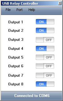
USB Relay Controller
Allows to control eight lights / appliances through USB IO Board. Microcontroller Port-B PINs are buffered by BC549 transistors and drive 12V / 10A relays.
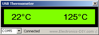
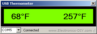
USB Thermometer
USB Thermometer allows to measure temperature in two different locations. Two Microchip MCP9700 temperature sensors in standard TO-92 package are used to sample temperature and allow to measure temperature from -40 to +125 Celsius degrees. Simply connect to a PC computer via standard USB cable and temperature readings will be displayed using included USB Thermometer software. USB Thermometer takes power directly from USB port and does not need external power supply. Temperature readings can be displayed in both Fahrenheit and Celsius degrees.
USB Thermometer software comes with Data Logger feature. Date, time and temperature readings are saved to a text file and can be used to create various graphs via Microsoft Excel or any other statistical software. The software will log temperature every x amount of time which can be set from a second up to a day.
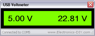
USB Voltmeter
USB Voltmeter has two voltage inputs for measuring voltage from 0V up to 500V. Simply connect to a PC computer via standard USB cable and voltage readings will be displayed via included USB Voltmeter software. USB Voltmeter takes power directly from USB port and does not need external power supply.
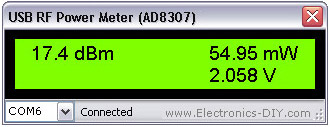
USB 0-500MHz RF Power Meter (AD8307)
AD8307 USB 0-500MHz RF Power Meter allows to measure the power of transmitters from 1nW to 2W. Output is displayed in dBm, Watts (nW, uW, mW and W range) as well as input voltage. USB RF Power Meter is based on popular AD8307 watt meter IC and PIC18F2550 microcontroller. Instead of using LCD display module the meter connects to a PC via USB port and displays measurements on a computer via USB RF Power Meter software. The software settings can be changed to use 10-50dBm attenuator and thus allowing to measure higher RF power than 2W.
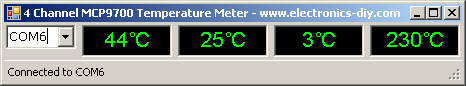
4-Channel MCP9700 Temperature Meter
Output of MCP9700 temerature sensors (in TO-92 package) is directly connected to ports A0, A1, A2 & A3 (PIN2, PIN3, PIN4, PIN5). Sensors draw +5V power directly from USB port. Temperature is sampled every second and is displayed in either Celsius or Fahrenheit degrees. While testing MCP9700 we pushed it over the limit and were surprised that the sensor was still measuring temperature at over 230 degrees Celsius. That's very impressive for such a relatively inexpensive sensor!
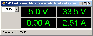
USB Volt / Ampere Meter

2-Channel USB Volt / Ampere Meter
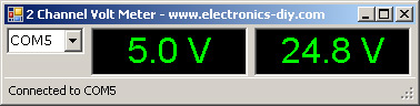
2-Channel USB Volt Meter
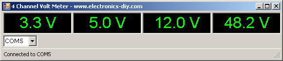
4-Channel USB Volt Meter
USB Relay Countdown Timer
USB Relay Countdown Timer can turn appliance OFF or ON after specified time. Countdown timer can be used as an exposure timer for UV light boxes, photography, egg timer, and many other projects. The countdown time can count from up to 99999 hours.

USB Relay Timer
USB Relay Timer can be programmed to turn relay ON and OFF at specified time during the day. Timer can turn off after the relay is powered off or be repeated daily.

USB Temperature Meter / Logger with Temperature Chart
USB Thermostat Controller
USB LCD Controller
USB Stepper Motor Controller
USB RGB LED Controller / Driver
USB CNC Controller
|
Windows Drivers
Using USB IO Board under Linux / Ubuntu
| |
Here's how to control USB IO Board under Linux Ubuntu.
Step 1: Plug in USB IO Board. It should appear at /dev/ttyACM0 or /dev/ttyACM1 - go take a look.
Step 2: Create a symbolic link from /dev/ttyS3 to /dev/ttyACM0 so gtkterm can talk to it.
Step 3: Run up gtkterm, connect to /dev/ttyS3, type "V" without the quotes and press ENTER. You should get back the firmware version and this proves that everything is working fine.
Controlling USB IO Board remotely over the internet using PHP under Linux Ubuntu:
<?php
include "php_serial.class.php"; // Let's start the class
$serial = new phpSerial;
// First we must specify the device. This works on both linux and windows (if
// your linux serial device is /dev/ttyS0 for COM1, etc)
$serial->deviceSet("/dev/ttyS3");
// Then we need to open it
$serial->deviceOpen();
// To write into
$serial->sendMessage("V\n");
// Or to read from
$read = $serial->readPort();
echo "output : \n $read \n";
// If you want to change the configuration, the device must be closed
$serial->deviceClose();
?>
 Download php_serial.class.php Download php_serial.class.php
Note: Right-click on the link & select "Save Link As" to save it to your computer. |
USB IO Board Kit
| |
USB IO Board kit with programmed and ready to use PIC18F2455 / PIC18F2550 microcontroller is available at Electronics-DIY store. Please see the link for more details. |
Related Links
|
|
|
| |
Accurate LC Meter
Build your own Accurate LC Meter (Capacitance Inductance Meter) and start making your own coils and inductors. This LC Meter allows to measure incredibly small inductances making it perfect tool for making all types of RF coils and inductors. LC Meter can measure inductances starting from 10nH - 1000nH, 1uH - 1000uH, 1mH - 100mH and capacitances from 0.1pF up to 900nF. The circuit includes an auto ranging as well as reset switch and produces very accurate and stable readings. |
|
PIC Volt Ampere Meter
Volt Ampere Meter measures voltage of 0-70V or 0-500V with 100mV resolution and current consumption 0-10A or more with 10mA resolution. The meter is a perfect addition to any power supply, battery chargers and other electronic projects where voltage and current must be monitored. The meter uses PIC16F876A microcontroller with 16x2 backlighted LCD. |
|
|
|
60MHz Frequency Meter / Counter
Frequency Meter / Counter measures frequency from 10Hz to 60MHz with 10Hz resolution. It is a very useful bench test equipment for testing and finding out the frequency of various devices with unknown frequency such as oscillators, radio receivers, transmitters, function generators, crystals, etc. |
|
1Hz - 2MHz XR2206 Function Generator
1Hz - 2MHz XR2206 Function Generator produces high quality sine, square and triangle waveforms of high-stability and accuracy. The output waveforms can be both amplitude and frequency modulated. Output of 1Hz - 2MHz XR2206 Function Generator can be connected directly to 60MHz Counter for setting precise frequency output. |
|
|
|
BA1404 HI-FI Stereo FM Transmitter
Be "On Air" with your own radio station! BA1404 HI-FI Stereo FM Transmitter broadcasts high quality stereo signal in 88MHz - 108MHz FM band. It can be connected to any type of stereo audio source such as iPod, Computer, Laptop, CD Player, Walkman, Television, Satellite Receiver, Tape Deck or other stereo system to transmit stereo sound with excellent clarity throughout your home, office, yard or camp ground. |
|
USB IO Board
USB IO Board is a tiny spectacular little development board / parallel port replacement featuring PIC18F2455/PIC18F2550 microcontroller. USB IO Board is compatible with Windows / Mac OSX / Linux computers. When attached to Windows IO board will show up as RS232 COM port. You can control 16 individual microcontroller I/O pins by sending simple serial commands. USB IO Board is self-powered by USB port and can provide up to 500mA for electronic projects. USB IO Board is breadboard compatible. |
|
|
|
|
ESR Meter / Capacitance / Inductance / Transistor Tester Kit
ESR Meter kit is an amazing multimeter that measures ESR values, capacitance (100pF - 20,000uF), inductance, resistance (0.1 Ohm - 20 MOhm), tests many different types of transistors such as NPN, PNP, FETs, MOSFETs, Thyristors, SCRs, Triacs and many types of diodes. It also analyzes transistor's characteristics such as voltage and gain. It is an irreplaceable tool for troubleshooting and repairing electronic equipment by determining performance and health of electrolytic capacitors. Unlike other ESR Meters that only measure ESR value this one measures capacitor's ESR value as well as its capacitance all at the same time. |
|
Audiophile Headphone Amplifier Kit
Audiophile headphone amplifier kit includes high quality audio grade components such as Burr Brown OPA2134 opamp, ALPS volume control potentiometer, Ti TLE2426 rail splitter, Ultra-Low ESR 220uF/25V Panasonic FM filtering capacitors, High quality WIMA input and decoupling capacitors and Vishay Dale resistors. 8-DIP machined IC socket allows to swap OPA2134 with many other dual opamp chips such as OPA2132, OPA2227, OPA2228, dual OPA132, OPA627, etc. Headphone amplifier is small enough to fit in Altoids tin box, and thanks to low power consumption may be supplied from a single 9V battery. |
|
|
|
|
|
Arduino Prototype Kit
Arduino Prototype is a spectacular development board fully compatible with Arduino Pro. It's breadboard compatible so it can be plugged into a breadboard for quick prototyping, and it has VCC & GND power pins available on both sides of PCB. It's small, power efficient, yet customizable through onboard 2 x 7 perfboard that can be used for connecting various sensors and connectors. Arduino Prototype uses all standard through-hole components for easy construction, two of which are hidden underneath IC socket. Board features 28-PIN DIP IC socket, user replaceable ATmega328 microcontroller flashed with Arduino bootloader, 16MHz crystal resonator and a reset switch. It has 14 digital input/output pins (0-13) of which 6 can be used as PWM outputs and 6 analog inputs (A0-A5). Arduino sketches are uploaded through any USB-Serial adapter connected to 6-PIN ICSP female header. Board is supplied by 2-5V voltage and may be powered by a battery such as Lithium Ion cell, two AA cells, external power supply or USB power adapter. |
|
200m 4-Channel 433MHz Wireless RF Remote Control
Having the ability to control various appliances inside or outside of your house wirelessly is a huge convenience, and can make your life much easier and fun. RF remote control provides long range of up to 200m / 650ft and can find many uses for controlling different devices, and it works even through the walls. You can control lights, fans, AC system, computer, printer, amplifier, robots, garage door, security systems, motor-driven curtains, motorized window blinds, door locks, sprinklers, motorized projection screens and anything else you can think of. |
|
|
|