HOME     STORE     BLOG     SCHEMATICS     TUTORIALS     DOWNLOADS     CONTACT

DTMF Decoder Using MT8870
 
DTMF Decoder Using MT8870


DTMF Decoder Using MT8870


This circuit detects the dial tone from a telephone line and decodes the keypad pressed on the remote telephone. The dial tone we heard when we pick up the phone set is call Dual Tone Multi-Frequency, DTMF in short. The name was given because the tone that we heard over the phone is actually make up of two distinct frequency tone, hence the name dual tone. The DTMF tone is a form of one way communication between the dialer and the telephone exchange. A complete communication consist of the tone generator and the tone decoder. In this article, we are use the IC MT8870DE, the main component to decode the input dial tone to 5 digital output. These digital bits can be interface to a computer or microcontroller for further application eg. remote control, phone line transfer operation, LEDs, etc...


DTMF Decoder Using MT8870

In the early days, our phone system used to be operated by human operator in a telephone exchange room. The caller will pick up the phone, giving instruction to the operator to connect their line to the destination over the other end of the telephone. As more and more people find phone technology a useful communication tools, line connection use human operator has become a tedious task.

As technology matures, pulse/dial tone method was inverted for telephony communication. It uses electronics and computer to assist in the phone line connection. Basically on the caller side, it is a dial tone generator. When a key is being pressed on the matrix keypad, it generate a unique tone consisting of two audible tone frequency. For example, if the key '1' is being press on the phone, the tone you hear is actually consist of a 697hz & 1209hz sine signal. Pressing key '9' will generate the tone form by 852hz & 1477hz. The frequency use in the dial tone system is of audible range suitable for transmission over the telephone cable.

On the telephone exchange side, it has a decoder circuit to decode the tone to digital code. For example, the tone of 941hz + 1336hz will be decoded as binary '1010' as the output. This digital output will be read in by a computer, which will then act as a operator to connect the caller's telephone line to the designated phone line. The telephone exchange center will generate a high voltage signal to the receiving telephone, so as to ring the telephone bell, to notified the receiving user that there is an incoming call.

This project article focus on a simple DTMF (dual tone multi-frequency) decoder circuit. This circuit can be interface to a computer, allowing caller to computer interaction. Many communication application can be build for example, a computerize call receiving/diverting phone network system. Remote control to Home/Office electrical appliances using a telephone network.

DTMF is a popular project especially in DSP (digital signal processing) subject. DSP software algorithm can be implement to generate as well as to decode DTMF tone. It is very interesting, and I will try to cover that aspect in near future. For now we do the hardware way.
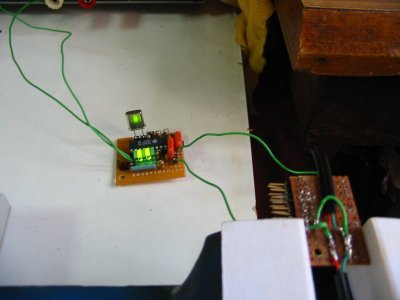
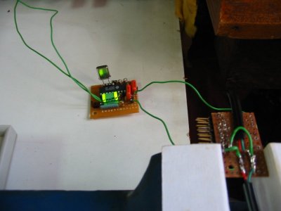
DTMF Circuits

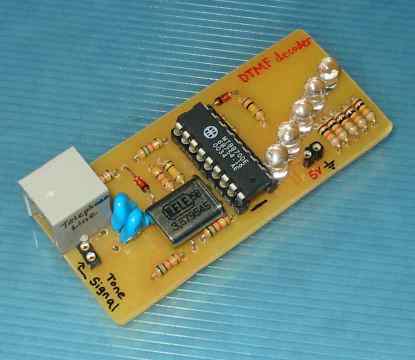
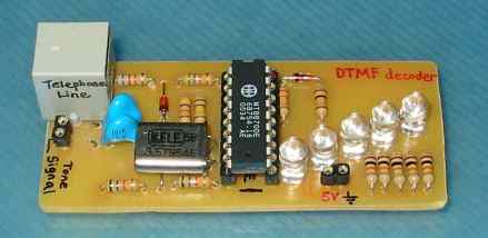
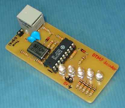
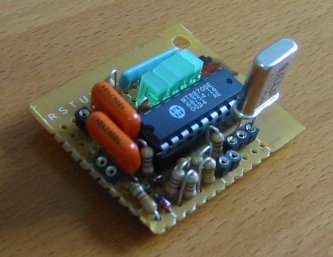
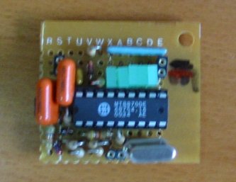
This the first DTMF circuit I build. Very small, roughly about my thumb size.


Output Logic behavior from the DTMF decoder IC.

no button press
TOE: Logic 0
Q4: Logic 0
Q3: Logic 0
Q2: Logic 0
Q1: Logic 0

'1' press and hold
TOE: Logic 1
Q4: Logic 0
Q3: Logic 0
Q2: Logic 0
Q1: Logic 1

release from button '1'
TOE: Logic 0
Q4: Logic 0
Q3: Logic 0
Q2: Logic 0
Q1: Logic 1

'2' press and hold
TOE: Logic 1
Q4: Logic 0
Q3: Logic 0
Q2: Logic 1
Q1: Logic 0

release from button '2'
TOE: Logic 0
Q4: Logic 0
Q3: Logic 0
Q2: Logic 1
Q1: Logic 0

'0' press and hold
TOE: Logic 1
Q4: Logic 1
Q3: Logic 0
Q2: Logic 1
Q1: Logic 0

Detection of dial tones is reflected on the bit TOE, while the output Q4, Q3, Q2, Q1 indicate the dial tone that is being detected on the telephony system. A complete table of the decoded digital output for individual dial tone is available in the coming section.

Key Tone Output Logic
Q4 Q3 Q2 Q1
1 0 0 0 1
2 0 0 1 0
3 0 0 1 1
4 0 1 0 0
5 0 1 0 1
6 0 1 1 0
7 0 1 1 1
8 1 0 0 0
9 1 0 0 1
0 1 0 1 0
* 1 0 1 1
# 1 1 0 0
A 1 1 0 1
B 1 1 1 0
C 1 1 1 1
D 0 0 0 0


These are the decoder output table for the given dial tone detected. Notice that there are key tone for A B C and D. These are special tone which are normally not found on our telephone. It is a common standard build into the decoder chip.

The circuit is relatively simple and straight forward, and all components can be easily found.

Schematics and BOM is provided below for your reference.

Bill of Material (BOM)
Part# Description Value Qty
C1, C2 Capacitor should be 100nF not 100pF.
100pF, 250V x2
D1 High Conductance Fast Diode 1N4148 x1
D2, D3 1.3 Watt Power Zener Diode Zener 5.6V x2
DS1, DS2, DS3, DS4, DS5 Typical RED GaAs LED x5
R1, R2 Resistor 56KΩ x2
R3 Resistor 150KΩ x1
R4 Resistor 47KΩ x1
R5 Resistor 330KΩ x1
R6 Resistor 100KΩ x1
R7 Resistor 68KΩ x1
R8, R9 Resistor 56KΩ x2
R10, R11, R12, R13, R14 Resistor 470Ω x5
U1 Integrated DTMF Receiver MT8870DE x1
U1 IC holder 18 pins x1
Y1 Crystal Oscillator 3.5795Mhz x1
JP1, JP2 Header, 2-Pin x2

Telephone Ring Detector Circuit Interface to Microcontroller.

Other DTMF Tone Generator or dialer chips, NTE1690, TCM5589N, TP5089N, 5088, 4089 and LC7366.
Other DTMF Tone Decoder chips 8870, SSI-202, LC7385 and KT3170.
Other DTMF Tone Generator + Decoder, 8888, 8889, 8880, HT9170C.

You may purchase MT8870 chips and 3.5795MHz crystals at http://electronics-diy.com/store.php?sel=ics&sub=remote_control


DTMF Decoder Using MT8870


DTMF Decoder Using MT8870


DTMF Decoder Using MT8870

DTMF Decoder Using MT8870

DTMF Decoder Using MT8870

DTMF Decoder Using MT8870

DTMF Decoder Using MT8870

DTMF Decoder Using MT8870

DTMF Decoder Using MT8870

DTMF Decoder Using MT8870


Accurate LC Meter Capacitance Inductance Meter with 16F628 and LCD
Volt Ampere Meter with 16F876 Microcontroller and LCD display
 
Accurate LC Meter

Build your own Accurate LC Meter (Capacitance Inductance Meter) and start making your own coils and inductors. This LC Meter allows to measure incredibly small inductances making it perfect tool for making all types of RF coils and inductors. LC Meter can measure inductances starting from 10nH - 1000nH, 1uH - 1000uH, 1mH - 100mH and capacitances from 0.1pF up to 900nF. The circuit includes an auto ranging as well as reset switch and produces very accurate and stable readings.
PIC Volt Ampere Meter

Volt Ampere Meter measures voltage of 0-70V or 0-500V with 100mV resolution and current consumption 0-10A or more with 10mA resolution. The meter is a perfect addition to any power supply, battery chargers and other electronic projects where voltage and current must be monitored. The meter uses PIC16F876A microcontroller with 16x2 backlighted LCD.

50MHz 60MHz Frequency Meter / Counter with 16F628 & LCD
1Hz - 2MHz XR2206 Function Generator
60MHz Frequency Meter / Counter

Frequency Meter / Counter measures frequency from 10Hz to 60MHz with 10Hz resolution. It is a very useful bench test equipment for testing and finding out the frequency of various devices with unknown frequency such as oscillators, radio receivers, transmitters, function generators, crystals, etc.
1Hz - 2MHz XR2206 Function Generator

1Hz - 2MHz XR2206 Function Generator produces high quality sine, square and triangle waveforms of high-stability and accuracy. The output waveforms can be both amplitude and frequency modulated. Output of 1Hz - 2MHz XR2206 Function Generator can be connected directly to 60MHz Counter for setting precise frequency output.

BA1404 HI-FI Stereo FM Transmitter
USB IO Board PIC18F2455 / PIC18F2550
BA1404 HI-FI Stereo FM Transmitter

Be "On Air" with your own radio station! BA1404 HI-FI Stereo FM Transmitter broadcasts high quality stereo signal in 88MHz - 108MHz FM band. It can be connected to any type of stereo audio source such as iPod, Computer, Laptop, CD Player, Walkman, Television, Satellite Receiver, Tape Deck or other stereo system to transmit stereo sound with excellent clarity throughout your home, office, yard or camp ground.
USB IO Board

USB IO Board is a tiny spectacular little development board / parallel port replacement featuring PIC18F2455/PIC18F2550 microcontroller. USB IO Board is compatible with Windows / Mac OSX / Linux computers. When attached to Windows IO board will show up as RS232 COM port. You can control 16 individual microcontroller I/O pins by sending simple serial commands. USB IO Board is self-powered by USB port and can provide up to 500mA for electronic projects. USB IO Board is breadboard compatible.

ESR Meter / Transistor Tester Kit
Audiophile Headphone Amplifier Kit
 
ESR Meter / Capacitance / Inductance / Transistor Tester Kit

ESR Meter kit is an amazing multimeter that measures ESR values, capacitance (100pF - 20,000uF), inductance, resistance (0.1 Ohm - 20 MOhm), tests many different types of transistors such as NPN, PNP, FETs, MOSFETs, Thyristors, SCRs, Triacs and many types of diodes. It also analyzes transistor's characteristics such as voltage and gain. It is an irreplaceable tool for troubleshooting and repairing electronic equipment by determining performance and health of electrolytic capacitors. Unlike other ESR Meters that only measure ESR value this one measures capacitor's ESR value as well as its capacitance all at the same time.
Audiophile Headphone Amplifier Kit

Audiophile headphone amplifier kit includes high quality audio grade components such as Burr Brown OPA2134 opamp, ALPS volume control potentiometer, Ti TLE2426 rail splitter, Ultra-Low ESR 220uF/25V Panasonic FM filtering capacitors, High quality WIMA input and decoupling capacitors and Vishay Dale resistors. 8-DIP machined IC socket allows to swap OPA2134 with many other dual opamp chips such as OPA2132, OPA2227, OPA2228, dual OPA132, OPA627, etc. Headphone amplifier is small enough to fit in Altoids tin box, and thanks to low power consumption may be supplied from a single 9V battery.
 

Arduino Prototype Kit
RF Remote Control 433MHz Four Channel
 
Arduino Prototype Kit

Arduino Prototype is a spectacular development board fully compatible with Arduino Pro. It's breadboard compatible so it can be plugged into a breadboard for quick prototyping, and it has VCC & GND power pins available on both sides of PCB. It's small, power efficient, yet customizable through onboard 2 x 7 perfboard that can be used for connecting various sensors and connectors. Arduino Prototype uses all standard through-hole components for easy construction, two of which are hidden underneath IC socket. Board features 28-PIN DIP IC socket, user replaceable ATmega328 microcontroller flashed with Arduino bootloader, 16MHz crystal resonator and a reset switch. It has 14 digital input/output pins (0-13) of which 6 can be used as PWM outputs and 6 analog inputs (A0-A5). Arduino sketches are uploaded through any USB-Serial adapter connected to 6-PIN ICSP female header. Board is supplied by 2-5V voltage and may be powered by a battery such as Lithium Ion cell, two AA cells, external power supply or USB power adapter.
200m 4-Channel 433MHz Wireless RF Remote Control

Having the ability to control various appliances inside or outside of your house wirelessly is a huge convenience, and can make your life much easier and fun. RF remote control provides long range of up to 200m / 650ft and can find many uses for controlling different devices, and it works even through the walls. You can control lights, fans, AC system, computer, printer, amplifier, robots, garage door, security systems, motor-driven curtains, motorized window blinds, door locks, sprinklers, motorized projection screens and anything else you can think of.
 

Electronics-DIY.com © 2002-2024. All Rights Reserved.