| |
FM Radio Receiver using TDA7088 |
|
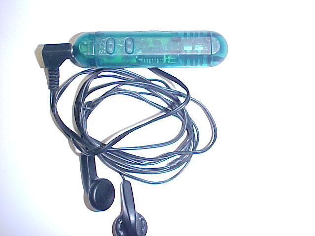
This tiny receiver is not much bigger than an AA cell. It is powered off two LR44 button cells, which are expensive and I assume wouldn't last terribly long. I'll be on the lookout for LR44's at the markets and $2 shops now that I've got this radio! As with all these sorts of radios, the headphone lead functions as the aerial. Supplied with this receiver were a pair of those awful "in-the-ear" type of miniature type earphones. Apart from the appalling sound quality, they are insensitive, unhygenic and dirty, fragile, and do not block out external sounds. So, I use the normal kind of headphones instead.
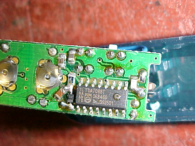
The enclosure is all clipped together, and once I'd opened it, sure enough, a TDA7088T was visible.
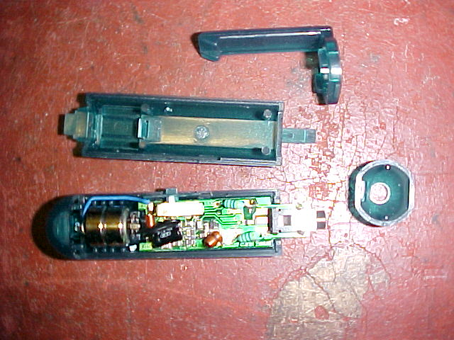
The audio amp appears to be one transistor; ie. single ended class A. I don't know what current it's drawing so I can't say whether it's consuming much more battery current than a class B amp would. In any case I would prefer AAA cells rather than the LR44's.
The power switch is a minature slide switch on the side, which has an extra position for volume. This is obviously done to avoid a space consuming potentiometer. So, we have only two levels of volume; full and something a bit less.
How well does it work? Quite well actually. Performance is the same as the TDA7000 IC in terms of sensitivity and sound quality. However, the TDA7088 has the mute permanently enabled so some weaker stations that could otherwise be received with a TDA7000 or TDA7010T cannot be received on the TDA7088T. Also, the headphone lead aerial is not as efficient as a 75cm telescopic aerial so this needs to be taken into account.
The scanning circuit works very well, there is virtually no waiting for the radio to find the next occupied frequency. Once you have reached the 108Mc/s limit, you have to press "reset" to get back to the 88Mc/s end of the band. It does not automatically do this like a PLL type of circuit would.
These TDA7088 receivers are very common in $2 shops (look for the "scan" & "reset" buttons), and you certainly shouldn't pay more than $5 for one. Most of them use the Chinese clone of the TDA7088; the SC1088. More often than not, these cheap auto scan FM receivers also incorporate a torch. Some also incorporate an AM receiver. This invariably uses a TRF circuit based around an MK484 (ZN414). Variable condenser tuning is used with these sets, on both AM and FM. Unfortunately, AM sensitivity is poor because of the very small ferrite loopstick aerial. They're a strictly "local station only" affair as far as AM goes. Sound quality is good, however, as there is only one tuned circuit (i.e. the ferrite loopstick).
The electronic diagram of the monophonic FM receiver made with TDA7088T is shown on Pic.4.12. If built with SMD components it can be placed in a matchbox, altogether with two button-type batteries. The operating principle of this device is given in the previous chapter. The only thing new is a very simple audio amplifier made with BC547 transistor, which is loaded by cheap 16-Ohm headphones. The telescopic antenna is used, as on Pic.4.8.
Small mishap of this receiver is that it has no indication of station tuning. This problem can be solved by adding a small voltmeter in parallel to the BB909, whose scale is graduated in MHz, as described in the Appendix. This solution is not appropriate for the miniature receiver, since the voltmeter that has the scale that is big enough takes too much space. It is in this case better using a manual tuning instead of automatic. Such solution is given on Pic.4.13.
The tuning is done via the variable capacitor C with numbers written on its button, similar to that on Pic.3.11. It is most simple to use numbers from 1 to 10. The variable capacitor is like the one on Pic.4.8. Some experimenting is to be done with capacitances of Cx and Cy, in order to cover the entire reception bandwidth, from 88 till 108 MHz.
The AFC (Automatic Frequency Control) of the local oscillator is accomplished with BA483 diode, obtaining that station’s position on scale does not “walk” over the scale.
The complete radio receiver should still have a loudspeaker. Electronic diagram of such receiver made with TDA7088T is given on Pic.4.14. As one can see, that is a receiver from Pic.4.12 with an audio receiver made with LM386 IC.
Maximum value of the DC supply voltage for the TDA7088T is 5V, therefore if using a 4.5 V battery the LM386 will work with reduced output power, the D2 diode and C15 capacitor should be omitted, and R4 should be short-circuited.
If higher voltage battery is used, the voltage stabilizer, comprised by the aforementioned components, has to be activated. D2 is a Zener diode with 3 V Zener voltage. The optimum value of R4 is found experimentally: in order to make the power consumption as low as possible it should have the resistance as big as possible, while simultaneously keeping the voltage on Pin 4 about 3 V and the device working well within the entire reception bandwidth (One should start with, say, R4=1.5 kOhm, and if the receiver operates well bigger resistance should be tried out, and if not smaller one, until the optimum value is found).
Pic.4.15. shows the PCB for the HF part of the receiver with TDA7088T, that is realized with ordinary components, instead of the SMD’s. Pic.4.15-a shows the board layout from the soldering (copper) side. All the components apart from TDA7088T are mounted on the opposite side of the board, their pins are put through the holes and soldered through the holes. The TDA is soldered on the copper side, directly onto the copper contacts. That is why it is being drawn in dashed line on pic.4.15-b, where the board layout on the component side is given.
* Pic.4.16-a shows 3x enlarged picture of the IC and the surrounding lines. The soldering procedure for SMD is as follows:
A thin tin layer is applied on the copper contacts where IC legs are to be soldered to. The firs legs to be soldered are the diagonally opposite ones, in this case No.1 and 9. A small cushion-shaped amount of tin (not profuse) is applied on the contacts where these pins are to be soldered (pic.4.17-a). The IC is placed in its position, with all the pins properly laid. Pin No.1 is pressed against the tin pillow with a top of a bodkin, with iron head simultaneously touching both the tin and the pin end. The tin gets melted, and the pin lies down on its place with the aid of the bodkin, and gets soldered.
It is now time to check out the positioning of the chip. If it needs to be corrected, the tin surrounding the pin No.1 is melted with iron tip and the chip position is quickly and carefully adjusted, in order not to overheat the pin. Soldering the pin No.9 is shown on Pic.4.17-b. First, the iron tip is simultaneously put on the top of the leg and the copper below it, so that both of them are heated. After app. half a second, the iron is slightly removed from the leg but remains on the copper contact. The tip of the tinol wire is then approached to touch the iron, the pin top and the copper contact at the same time. The wire gets melted and adheres to the copper and the pin, so it has to be constantly moved downwards. When enough tin is applied, the tinol wire is removed first, then the iron, and the pin No.9 is soldered. Once again you have to check whether all the pins are properly placed, and then they too are soldered as it was just described. The solders are OK if they look app. as on Pic.4.17-c.
* Pic.4.15-b contains the PCB component side layout. The pushbuttons we used here are Siemens, type BO2AMAP-2. The common housing contains, as one can see, two button switches, one of which is being used by this device. Any other pushbutton switches can also be used. In that case small modifications on the PCB lines would probably be necessary. The board is mounted fairly close to the box edge, so that the switch shafts are passing through the panel, and that the buttons can be mounted on the outside. The panel-mount switches can also be used, in which case they are connected to the board by wires (pic.4.15-e).
* Any audio amplifier described so far can be used, e.g. the one with LM386, as on pic.4.8.
* Instead of the antenna, a 20 cm piece of wire can also be utilized.
4.2.2.2. Stereophonic Receiver Built with TDA7088T
Stereophonic radio broadcast is performed in the ultra short waveband, from 88 MHz till 108 MHz. All radio transmitters operating in this range are stereophonic, but their signal is designed so that monophonic receivers can also read it, performing the compatibility. The readers that wish to get acquainted in more details with the stereophonic broadcast basics can refer to the “Radio Receivers” textbook, for the IV grade of the Electrotechnical Highschool.
Making an introduction to this part, a operating principle of the stereophonic radio receiver shall be considered, its block diagram shown on pic.4.18. Comparing this diagram with the one of the monophonic receiver given on pic.4.6, one may notice that they are identical, up to the block called "The Decoder". It means that, as already described, exiting the FM detector the LF signal is obtained, i.e. the information that was used to perform the frequency modulation in the transmitter. However, this is not an ordinary LF signal, but the one, called the "composed" (KS) or "multiplexed" (Mpx) signal. Besides the full-scale LF signal used by the monophonic receiver,
it also contains the so-called auxiliary signal which allows the separation of left (L) and right (R) channels in the stereophonic receiver. E.g. if a direct broadcast of some band music is performed, the left part of performers is being recorded with one microphone (the signal marked as L), whilst the right side is recorded with the other one (it’s a R signal). These two signals are being led in the FM transmitter in the stage called “the coder”. Exiting the coder we have the multiplexed signal Mpx which contains, in an indirect manner, both left (L) and right (R) signal. Frequency modulation of the transmitter is being performed with the Mpx signal. In the receiver, Mpx signal is obtained on the output of the FM Detector and is then led to the decoder. This stage plays a role complementary to the one of the coder in the transmitter, therefore two signals are exiting it, the L and D signal. They are being amplified over two identical audio amplifiers, then reproduced over two same loudspeakers. The listener can now hear the left half of the performers from the loudspeaker placed on its left, and the right half from the loudspeaker that is placed on its right. The performers that are situated in the middle of the orchestra are being equally reproduced from both loudspeakers, making an impression to the listener as if there’s a third loudspeaker, located in the middle, between the left and right one. Based on all this, the listener has a picture about the layout of the performers in space, which significantly improves the total musical impression.
Electronic circuit of a portable stereophonic radio receiver with headphones reproduction, made with TDA7088T is shown on pic.4.19. It is a receiver whose practical realization was described in the previous project, with decoder with TDA7040T and dual audio amplifier with TDA7050T blocks added, the latter was discussed in PE5.
* L3, L4 and L5 are HF chokes that allow for the headphones cable to be used as a reception antenna. This is accomplished by connecting one of the headphones’ contacts from the plug-in, over the 10 pF capacitor, to the point where, acc. to pic.4.14, the outside antenna is connected. The coils represent big resistance to the station signals, preventing them to “go to ground” over the 47 mF capacitor or over the TDA7050T output. Each coil has 3 quirks of the 0.2 mm CuL wire, threaded through ferrite pearls, as shown on detail in the right corner of the pic.4.19. If telescopic antenna is to be used, these coils should be omitted.
Related Links
Downloads
FM Radio Receiver using TDA7088 - Link
|
|
|
| |
Accurate LC Meter
Build your own Accurate LC Meter (Capacitance Inductance Meter) and start making your own coils and inductors. This LC Meter allows to measure incredibly small inductances making it perfect tool for making all types of RF coils and inductors. LC Meter can measure inductances starting from 10nH - 1000nH, 1uH - 1000uH, 1mH - 100mH and capacitances from 0.1pF up to 900nF. The circuit includes an auto ranging as well as reset switch and produces very accurate and stable readings. |
|
PIC Volt Ampere Meter
Volt Ampere Meter measures voltage of 0-70V or 0-500V with 100mV resolution and current consumption 0-10A or more with 10mA resolution. The meter is a perfect addition to any power supply, battery chargers and other electronic projects where voltage and current must be monitored. The meter uses PIC16F876A microcontroller with 16x2 backlighted LCD. |
|
|
|
60MHz Frequency Meter / Counter
Frequency Meter / Counter measures frequency from 10Hz to 60MHz with 10Hz resolution. It is a very useful bench test equipment for testing and finding out the frequency of various devices with unknown frequency such as oscillators, radio receivers, transmitters, function generators, crystals, etc. |
|
1Hz - 2MHz XR2206 Function Generator
1Hz - 2MHz XR2206 Function Generator produces high quality sine, square and triangle waveforms of high-stability and accuracy. The output waveforms can be both amplitude and frequency modulated. Output of 1Hz - 2MHz XR2206 Function Generator can be connected directly to 60MHz Counter for setting precise frequency output. |
|
|
|
BA1404 HI-FI Stereo FM Transmitter
Be "On Air" with your own radio station! BA1404 HI-FI Stereo FM Transmitter broadcasts high quality stereo signal in 88MHz - 108MHz FM band. It can be connected to any type of stereo audio source such as iPod, Computer, Laptop, CD Player, Walkman, Television, Satellite Receiver, Tape Deck or other stereo system to transmit stereo sound with excellent clarity throughout your home, office, yard or camp ground. |
|
USB IO Board
USB IO Board is a tiny spectacular little development board / parallel port replacement featuring PIC18F2455/PIC18F2550 microcontroller. USB IO Board is compatible with Windows / Mac OSX / Linux computers. When attached to Windows IO board will show up as RS232 COM port. You can control 16 individual microcontroller I/O pins by sending simple serial commands. USB IO Board is self-powered by USB port and can provide up to 500mA for electronic projects. USB IO Board is breadboard compatible. |
|
|
|
|
ESR Meter / Capacitance / Inductance / Transistor Tester Kit
ESR Meter kit is an amazing multimeter that measures ESR values, capacitance (100pF - 20,000uF), inductance, resistance (0.1 Ohm - 20 MOhm), tests many different types of transistors such as NPN, PNP, FETs, MOSFETs, Thyristors, SCRs, Triacs and many types of diodes. It also analyzes transistor's characteristics such as voltage and gain. It is an irreplaceable tool for troubleshooting and repairing electronic equipment by determining performance and health of electrolytic capacitors. Unlike other ESR Meters that only measure ESR value this one measures capacitor's ESR value as well as its capacitance all at the same time. |
|
Audiophile Headphone Amplifier Kit
Audiophile headphone amplifier kit includes high quality audio grade components such as Burr Brown OPA2134 opamp, ALPS volume control potentiometer, Ti TLE2426 rail splitter, Ultra-Low ESR 220uF/25V Panasonic FM filtering capacitors, High quality WIMA input and decoupling capacitors and Vishay Dale resistors. 8-DIP machined IC socket allows to swap OPA2134 with many other dual opamp chips such as OPA2132, OPA2227, OPA2228, dual OPA132, OPA627, etc. Headphone amplifier is small enough to fit in Altoids tin box, and thanks to low power consumption may be supplied from a single 9V battery. |
|
|
|
|
|
Arduino Prototype Kit
Arduino Prototype is a spectacular development board fully compatible with Arduino Pro. It's breadboard compatible so it can be plugged into a breadboard for quick prototyping, and it has VCC & GND power pins available on both sides of PCB. It's small, power efficient, yet customizable through onboard 2 x 7 perfboard that can be used for connecting various sensors and connectors. Arduino Prototype uses all standard through-hole components for easy construction, two of which are hidden underneath IC socket. Board features 28-PIN DIP IC socket, user replaceable ATmega328 microcontroller flashed with Arduino bootloader, 16MHz crystal resonator and a reset switch. It has 14 digital input/output pins (0-13) of which 6 can be used as PWM outputs and 6 analog inputs (A0-A5). Arduino sketches are uploaded through any USB-Serial adapter connected to 6-PIN ICSP female header. Board is supplied by 2-5V voltage and may be powered by a battery such as Lithium Ion cell, two AA cells, external power supply or USB power adapter. |
|
200m 4-Channel 433MHz Wireless RF Remote Control
Having the ability to control various appliances inside or outside of your house wirelessly is a huge convenience, and can make your life much easier and fun. RF remote control provides long range of up to 200m / 650ft and can find many uses for controlling different devices, and it works even through the walls. You can control lights, fans, AC system, computer, printer, amplifier, robots, garage door, security systems, motor-driven curtains, motorized window blinds, door locks, sprinklers, motorized projection screens and anything else you can think of. |
|
|
|