| |
Here's a really simple and inexpensive Power LED driver circuit. The circuit is a "constant current source", which means that it keeps the LED brightness constant no matter what power supply you use or surrounding environmental conditions you subject the LED's to.
Or to put in another way: "this is better than using a resistor". It's more consistent, more efficient, and more flexible. It's ideal for High-power LED's especially, and can be used for any number and configuration of normal or high-power LED's with any type of power supply.
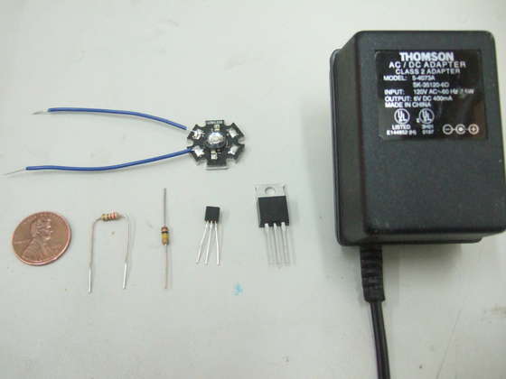
As a simple project, i've built the driver circuit and connected it to a high-power LED and a power-brick, making a plug-in light. Power LED's are now around $3, so this is a very inexpensive project with many uses, and you can easily change it to use more LED's, batteries, etc.
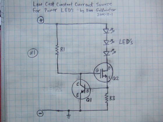
Circuit parts (refer to the schematic diagram)
R1: approximately 100k-ohm resistor (Yageo CFR-25JB series)
R3: current set resistor - see below
Q1: small NPN transistor (Fairchild 2N5088BU)
Q2: large N-channel FET (Fairchild FQP50N06L)
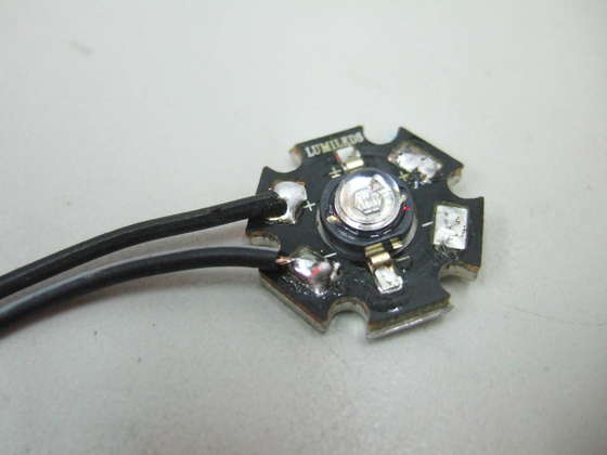
LED: power LED (Luxeon 1-watt white star LXHL-MWEC)
Other parts:
power source: I used an old "wall wart" transformer, or you could use batteries. to power a single LED anything between 4 and 6 volts with enough current will be fine. that's why this circuit is convenient! you can use a wide variety of power sources and it will always light up exactly the same.
heat sinks: here i'm building a simple light with no heatsink at all. that limits us to about 200mA LED current. for more current you need to put the LED and Q2 on a heatsink (see my notes in other power-led instructables i've done).
prototyping-boards: i didn't use a proto-board initially, but i built a second one after on a proto-board, there's some photos of that at the end if you want to use a proto-board.
selecting R3:
The circuit is a constant-current source, the value of R3 sets the current.
Calculations:
- LED current is set by R3, it is approximately equal to: 0.5 / R3
- R3 power: the power dissipated by the resistor is approximately: 0.25 / R3
I set the LED current to 225mA by using R3 of 2.2 ohms. R3 power is 0.1 watt, so a standard 1/4 watt resistor is fine.
Here i'll explain how the circuit works, and what the maximum limits are, you can skip this if you want.
Specifications:
input voltage: 2V to 18V
output voltage: up to 0.5V less than the input voltage (0.5V dropout)
current: 20 amps + with a large heatsink
Maximum limits:
the only real limit to the current source is Q2, and the power source used. Q2 acts as a variable resistor, stepping down the voltage from the power supply to match the need of the LED's. so Q2 will need a heatsink if there is a high LED current or if the power source voltage is a lot higher than the LED string voltage. with a large heatsink, this circuit can handle a LOT of power.
The Q2 transistor specified will work up to about 18V power supply. If you want more, look at my Instructable on LED circuits to see how the circuit needs to change.
With no heat sinks at all, Q2 can only dissipate about 1/2 watt before getting really hot - that's enough for a 200mA current with up to 3-volt difference between power supply and LED.
Circuit function:
- Q2 is used as a variable resistor. Q2 starts out turned on by R1.
- Q1 is used as an over-current sensing switch, and R3 is the "sense resistor" or "set resistor" that triggers Q1 when too much current is flowing.
- The main current flow is through the LED's, through Q2, and through R3. When too much current flows through R3, Q1 will start to turn on, which starts turning off Q2. Turning off Q2 reduces the current through the LED's and R3. So we've created a "feedback loop", which continuously tracks the current and keeps it exactly at the set point at all times.
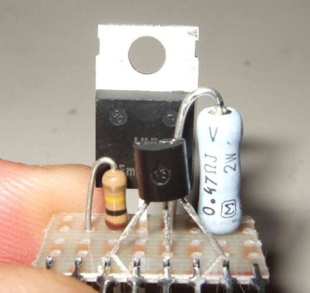
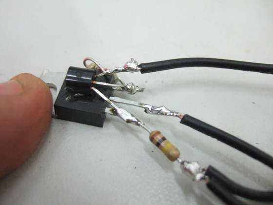
This circuit is so simple, i'm going to build it without a circuit board. i'll just connect the leads of the parts in mid-air! but you can use a small proto-board if you want (see photos at the end for an example).
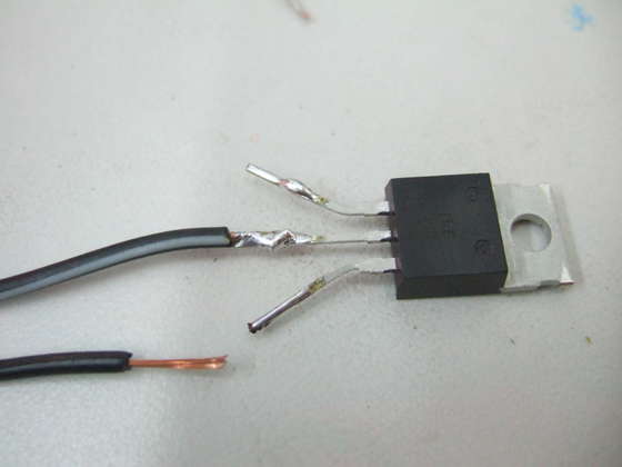
first, identify the pins on Q1 and Q2. laying the parts in front of you with the labels up and the pins down, pin 1 is on the left and pin 3 is on the right.
comparing to the schematic:
Q2:
G = pin 1
D = pin 2
S = pin 3
Q1:
E = pin 1
B = pin 2
C = pin 3
so: start by connecting the wire from the LED-negative to pin 2 of Q2
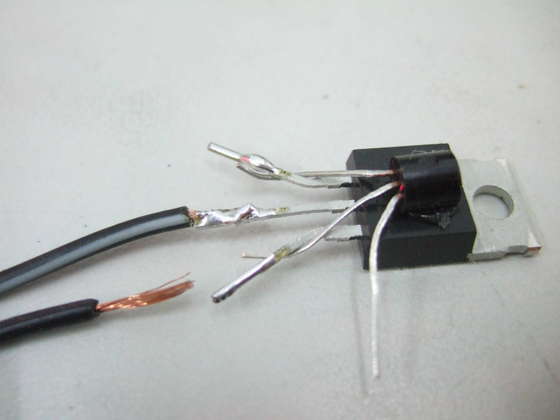
Now we'll start connecting Q1.
first, glue Q1 upside-down to the front of Q2 so that it is easier to work with. this has the added benefit that if Q2 gets very hot, it will cause Q1 to reduce the current limit - a safety feature!
- connect pin 3 of Q1 to pin 1 of Q2.
- connect pin 2 of Q1 to pin 3 of Q2.
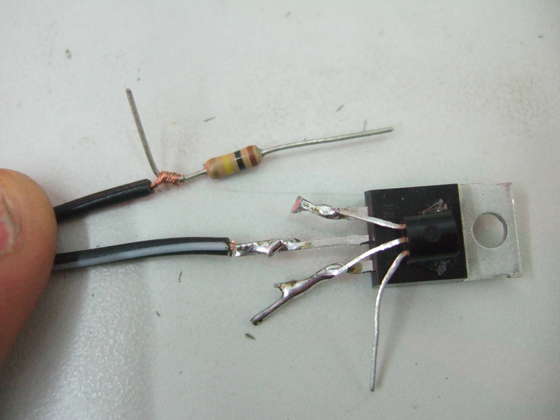
- solder resistor one leg of resistor R1 to that dangling LED-plus wire
- solder the other leg of R1 to pin 1 of Q2.
- attach the positive wire from the battery or power source to the LED-plus wire. it probably would have been easier to do that first actually.
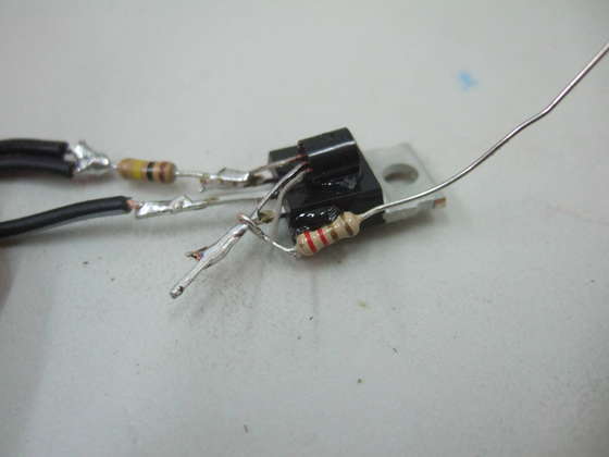
- glue R3 to the side of Q2 so it stays in place.
- connect one lead of R3 to pin 3 of Q2
- connect the other lead of R3 to pin 1 of Q1
now connect the negative wire from the power source to pin 1 of Q1.
you're done! we'll make it less flimsy in the next step.
now test the circuit by applying power. assuming it works, we just need to make it durable. an easy way is to put a large blob of silicone glue all over the circuit. this will make it mechanically strong and waterproof. just glob on the silicone, and make an effort to get rid of any air bubbles. i call this method: "BLOB-TRONICS". it doen't look like much, but it works really well and is cheap and easy.
also, tying the two wires together helps reduce strain on the wires also.
i've also added a photo of the same circuit, but on a proto-board (this one is "Capital US-1008", available at digikey), and with a 0.47-ohm R3.
Related Links
Downloads
Power LED Driver Circuit - Link
|
|
|
| |
Accurate LC Meter
Build your own Accurate LC Meter (Capacitance Inductance Meter) and start making your own coils and inductors. This LC Meter allows to measure incredibly small inductances making it perfect tool for making all types of RF coils and inductors. LC Meter can measure inductances starting from 10nH - 1000nH, 1uH - 1000uH, 1mH - 100mH and capacitances from 0.1pF up to 900nF. The circuit includes an auto ranging as well as reset switch and produces very accurate and stable readings. |
|
PIC Volt Ampere Meter
Volt Ampere Meter measures voltage of 0-70V or 0-500V with 100mV resolution and current consumption 0-10A or more with 10mA resolution. The meter is a perfect addition to any power supply, battery chargers and other electronic projects where voltage and current must be monitored. The meter uses PIC16F876A microcontroller with 16x2 backlighted LCD. |
|
|
|
60MHz Frequency Meter / Counter
Frequency Meter / Counter measures frequency from 10Hz to 60MHz with 10Hz resolution. It is a very useful bench test equipment for testing and finding out the frequency of various devices with unknown frequency such as oscillators, radio receivers, transmitters, function generators, crystals, etc. |
|
1Hz - 2MHz XR2206 Function Generator
1Hz - 2MHz XR2206 Function Generator produces high quality sine, square and triangle waveforms of high-stability and accuracy. The output waveforms can be both amplitude and frequency modulated. Output of 1Hz - 2MHz XR2206 Function Generator can be connected directly to 60MHz Counter for setting precise frequency output. |
|
|
|
BA1404 HI-FI Stereo FM Transmitter
Be "On Air" with your own radio station! BA1404 HI-FI Stereo FM Transmitter broadcasts high quality stereo signal in 88MHz - 108MHz FM band. It can be connected to any type of stereo audio source such as iPod, Computer, Laptop, CD Player, Walkman, Television, Satellite Receiver, Tape Deck or other stereo system to transmit stereo sound with excellent clarity throughout your home, office, yard or camp ground. |
|
USB IO Board
USB IO Board is a tiny spectacular little development board / parallel port replacement featuring PIC18F2455/PIC18F2550 microcontroller. USB IO Board is compatible with Windows / Mac OSX / Linux computers. When attached to Windows IO board will show up as RS232 COM port. You can control 16 individual microcontroller I/O pins by sending simple serial commands. USB IO Board is self-powered by USB port and can provide up to 500mA for electronic projects. USB IO Board is breadboard compatible. |
|
|
|
|
ESR Meter / Capacitance / Inductance / Transistor Tester Kit
ESR Meter kit is an amazing multimeter that measures ESR values, capacitance (100pF - 20,000uF), inductance, resistance (0.1 Ohm - 20 MOhm), tests many different types of transistors such as NPN, PNP, FETs, MOSFETs, Thyristors, SCRs, Triacs and many types of diodes. It also analyzes transistor's characteristics such as voltage and gain. It is an irreplaceable tool for troubleshooting and repairing electronic equipment by determining performance and health of electrolytic capacitors. Unlike other ESR Meters that only measure ESR value this one measures capacitor's ESR value as well as its capacitance all at the same time. |
|
Audiophile Headphone Amplifier Kit
Audiophile headphone amplifier kit includes high quality audio grade components such as Burr Brown OPA2134 opamp, ALPS volume control potentiometer, Ti TLE2426 rail splitter, Ultra-Low ESR 220uF/25V Panasonic FM filtering capacitors, High quality WIMA input and decoupling capacitors and Vishay Dale resistors. 8-DIP machined IC socket allows to swap OPA2134 with many other dual opamp chips such as OPA2132, OPA2227, OPA2228, dual OPA132, OPA627, etc. Headphone amplifier is small enough to fit in Altoids tin box, and thanks to low power consumption may be supplied from a single 9V battery. |
|
|
|
|
|
Arduino Prototype Kit
Arduino Prototype is a spectacular development board fully compatible with Arduino Pro. It's breadboard compatible so it can be plugged into a breadboard for quick prototyping, and it has VCC & GND power pins available on both sides of PCB. It's small, power efficient, yet customizable through onboard 2 x 7 perfboard that can be used for connecting various sensors and connectors. Arduino Prototype uses all standard through-hole components for easy construction, two of which are hidden underneath IC socket. Board features 28-PIN DIP IC socket, user replaceable ATmega328 microcontroller flashed with Arduino bootloader, 16MHz crystal resonator and a reset switch. It has 14 digital input/output pins (0-13) of which 6 can be used as PWM outputs and 6 analog inputs (A0-A5). Arduino sketches are uploaded through any USB-Serial adapter connected to 6-PIN ICSP female header. Board is supplied by 2-5V voltage and may be powered by a battery such as Lithium Ion cell, two AA cells, external power supply or USB power adapter. |
|
200m 4-Channel 433MHz Wireless RF Remote Control
Having the ability to control various appliances inside or outside of your house wirelessly is a huge convenience, and can make your life much easier and fun. RF remote control provides long range of up to 200m / 650ft and can find many uses for controlling different devices, and it works even through the walls. You can control lights, fans, AC system, computer, printer, amplifier, robots, garage door, security systems, motor-driven curtains, motorized window blinds, door locks, sprinklers, motorized projection screens and anything else you can think of. |
|
|
|