| |
This Field Strength Meter has been specially designed for our FM bugs. It is capable of detecting very low power transmitters and will assist enormously in peaking many of our FM transmitters that have a coil in the output stage that can be adjusted for optimum output.
Up to now, field strength meters have only been able to detect transmitters with an output of 100 milliwatts or higher, and for an output such as this, a simple circuit such as a meter and a coil is sufficient. But when it comes to a low power device, a simple circuit, with no amplification, is not suitable.
We spent more than 5 days building all the circuits we could find - that purported to be suitable for low-power transmitters, hoping to find one that would work.
Unfortunately none came anywhere near good enough so we had to design our own.
The circuit we came up with is shown above and it incorporates an RF amplifier, diode rectification, and a DC amplifier so that a movement from a multimeter (a movement is the 'meter' part of a multimeter) could be used as the readout. The heart of the design is a pair of diodes that are partially turned on via a resistor (the 100k sensitivity control) and this overcomes some of the .6v threshold of a diode.
You may not think .6v is very much but when you are talking in millivolt terms, it is 600 millivolts. The signal we are attempting to pick up produces one or two millivolts on the receiving antenna and if you need 600 millivolts to turn a diode ON, the field strength meter becomes very insensitive.
Our design overcomes this problem and produces a reading up to 10cm from a bug. This means you can adjust and peak a bug with the antenna fitted and get an accurate indication of the power it is producing.
Up to now you have had to rely on the "LED Power Meter” as described in a previous article and although it gives a good indication of the RF energy, it does not take into account the loading effect of the antenna.
The antenna loads the output stage of any transmitter and when you have a low power device, the antenna tends to detune the frequency slightly so that a slight re-peaking is necessary if you want to get maximum performance. The field strength meter will allow you to do this and get back the extra performance you may have lost.
HOW THE CIRCUIT WORKS
The circuit consists basically of an RF amplifier, diode rectifier and a DC amplifier. The first feature that may be new to you is the inductor in the antenna circuit. You may think it produces a short-circuit between the antenna and earth but the inductance of the 15 turn coil creates a voltage across it when the antenna picks up a signal. This voltage is fed to the base of the first transistor via a 47p capacitor and since the transistor is turned on via a 220k resistor, any signal from the 47p will be amplified by the transistor.
The RF amplifier has been designed to only have a gain at high frequencies. In our case this is at about 100MHz to 300MHz. The 300MHz is the upper limit due to the response of the RF transistor and the lower frequency is governed by the 100p bypass capacitor on the emitter.
It's impedance at 100MHz is 16 ohms and this gives the stage a gain of about 12. At 10MHz the reactance of the capacitor is 160 ohms and the gain of the stage drops to about 2.
This prevents low frequencies from being amplified and up-setting the reading.
By increasing the value of the emitter bypass capacitor, the gain of the stage will be increased but this is not desirable as it may cause excessive gain causing the front end to self-oscillate.
The inductor in the collector circuit separates the output signal from the power rail and increases the output amplitude slightly.
The low value coupling capacitor (100p) between the RF stage and diode pair is sufficient to transfer the energy as, don't forget, we are dealing with very high frequencies. The two diodes in the diode stage simply work as a rectifier and are partially forward biased via a 47k and 100k sensitivity control from the positive rail. But they are not turned on fully due to the base emitter junction of the DC amplifier transistor only allowing .6v to appear across them.
When a signal is passed into the diode pair, the negative excursions reduce the voltage across them and this begins to turn off the DC amplifier transistor and thus the needle on the meter drops. It requires about 300mV signal to start the process and with a gain of about 12 on the RF transistor, we need about 30 millivolts developed on the antenna circuit to start the detecting process.
This makes the Field Strength Meter only sensitive to nearby signals and prevents weaker signals from upsetting the reading.
The 10k pot connected to one end of the voltmeter sets the full-scale deflection for a 0-10v range on the multimeter.
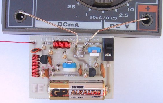
The circuit consumes about 3.5mA and with a lighter battery (50mAHr cells) the circuit will operate for more than 12 hours. A switch is provided to conserve the battery when not required and the board attaches to any multimeter via leads and paper clips that have been bent to suit the banana sockets on the meter.
Any old meter will do and it can have a sensitivity from 1k ohms per volt to 50k ohms per volt. The range we used in our prototype is 10v DC on a 30k ohms per volt meter however 12v, 15v or even 25v scale will be ok and the 25v range simply means the needle will not deflect as much, for the same RF detected.
You can even use an old, broken, multimeter providing the movement is not damaged. We have about 5 of these field strength meters, one for each worker, as everyone needs one to peak the devices we are making
We turned 5 broken multimeters into active service. It's one good way of using damaged equipment. It's amazing how the staff can blow up things, with the ohms range not working and the milliamp range burnt out.
I remember one firm had the same problem. They made all the staff spend every Friday afternoon repairing the test equipment but with the tight economics of today, we couldn't afford the luxury of providing half a day's holiday like this each week.
PARTS LIST
2 - 2k2
1 - 33k
1 - 47k
1 - 100k
1 - 220k
1 - 47p ceramic
2 - 100pceramics (101)
1 - 22n ceramic (223)
1 - 100n ceramic (104)
1 - 10k mini trim-pot
1 - 100k mini trim-pot
1 - BC 547 transistor
1 - PN 3563 RF transistor
2 - 1N4148 diodes
1 - 13t enamelled wire 3mrn dia coil
1 - 15t enamelled wire 3mm dia coil
1 - 12v lighter battery
1 - 25cm enamelled wire
1 - SPDT mini slide switch
2 - paper clips
1 - FIELD STRENGTH METER PCB
Extras:
1 - multimeter (0v -10v range)
CONSTRUCTION
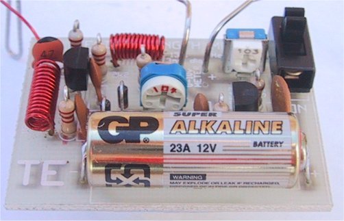
All the components, including the 12volt lighter battery and switch, mount on the PC board. The legend on the board shows where each part is placed arid we have found it important to avoid over-heating the diodes and transistors as they lose their peak performance and cause the circuit to become very insensitive. Follow the overlay on the PC board to see where everything is placed. The coils are pre-wound and are wound on a 3mm diameter Philips screwdriver (if you are making your own) and the wire size is not critical as they simply form a broad-band trap.
The antenna wire is enamelled to prevent it touching the active components of the bug you are testing.
We needn’t say any more about construction as you will obviously know how to put it together.
SETTING UP
Solder the paper clips to the board as shown in the photo and bend them to suit the sockets on the multimeter. Turn the "sensitivity" control (100k pot) to minimum resistance and switch the circuit ON. Turn the "Set full scale deflection" pot (10k) to give full deflection on the meter. Now turn the sensitivity pot until the needle just starts to "dip."
At this point the circuit is the most sensitive as the DC amplifier transistor is just turned on and any signal appearing on the diodes will reduce the voltage appearing on the top of them and turn the transistor off - the needle on the meter will begin to drop. The Field Strength Meter is now ready for use.
USING THE FIELD STRENGTH METER
This project will help you get the best silt of any transmitter. It will give an accurate readout because it does not connect to the transmitter but registers the strength of the field AT A DISTANCE.
The way it is used is to set up the antenna of the Field Strength Meter in the same plane as the transmitting antenna (to get the best pick-up) and at a distance that just causes the needle on the meter to deflect.
The meter is wired as a "DIP" meter and the needle deflects towards zero as the field strength increases. Place the bug to be peaked on the test bench, with the antenna out-stretched and bring the receiving antenna so that the needle just starts to dip.
Peak the circuit a small amount and take your hands away so that they don't upset the reading, and watch the needle. As the output increases, the needle dips further. By maintaining the exact same distance between bug and meter, you can compare one bug with another.
It's the fastest way of determining the output without doing a "field test."
IF IT DOESN'T WORK
As with all our projects, they work be cause we have actually built them and checked their performance. If yours doesn't work, the first thing to do is check the value of the components against the overlay on the board.
Two components in the wrong place can make a huge difference and a circuit like this is fairly critical as the biasing must be correct.
Secondly, make sure all the parts are fitted and nothing has been missed. Also make sure all the parts have been soldered neatly and cleanly.
We still get projects sent to us for repair where one or more leads have not been soldered and obviously the project could never work.
Next you can make a few voltage readings. Although they don't tell you too much, it is a fast way of determining if a stage has the correct DC conditions.
The voltages:
RF Stage:
Collector: 6.1v
Base: 5.8v
Emitter: 5.2v
DC stage:
Collector: 0.2v
Base: 0.65v
Emitter: 0v
If these check out ok, you should make a few further DC tests. If the meter swings full scale at power-up, you should short between base and emitter of the BC 547 to see the needle falls to zero. This will show the transistor is working ok. If not, the transistor may be shorted.
Next remove the 47k on the diode pair. This will also cause the needle to move down-scale and show the biasing network is working. It is more difficult to test the RF stage and merely probing around the stage with a meter or CR0, will pick up hum and cause the needle to deflect.
The frequency of operation of this circuit makes it important that it is built on the correct PC board.
We cannot guarantee "breadboard" jobs or circuits made with your own components as so many variables creep in.
Things like different markings on capacitors, different RF transistors or signal diodes could make the difference between success and failure.
If you know what you are doing, that's fine - you can use your own components. But if you intend to learn from our projects, don't take any chances.
This project is so important that we don't want you to miss out. With a field strength meter you can carry out experiments that would take a chapter of a book to explain. Here's one:
EXPERIMENTING
Take the Voyager project and connect 30cm of tinned copper wire to the antenna point on the PC board. Hold the Field Strength Meter in your hand (keep away from the actual circuit by holding the multimeter) and bring the receiving antenna near the Voyager antenna, without touching it. As you move up and down the Voyager antenna, watch the needle.
It will show that energy is not radiated uniformly from the antenna but has a maximum and minimum value. It is for you to see where these occur. Measure the length of the antenna and plot the results. Cut 2cm off the antenna and repeat the tests. Fit a 175cm antenna to the bug and repeat the tests.
This will give you a good understanding of the phenomenon of electromagnetic radiation.
There are lots of other things you can test with this project.
The Field Strength Meter Mkll is presented in the next article and has the advantage of a tuned front end and 3-LED readout. This will enable you to not only peak transmitters but also find the frequency on which they are operating.
It detects in the range 75MHz to 140MHz enabling you to design and build transmitters capable of transmitting off the normal broadcast band.
But don't put off building this project as you will need both of them as they have different capabilities. And you also need the LED Power Meter.
Test equipment is very important when working with RF so don't put it off any longer, start now and build up your range of gear.
Related Links
Downloads
Field Strength Meter - Link
|
|
|
| |
Accurate LC Meter
Build your own Accurate LC Meter (Capacitance Inductance Meter) and start making your own coils and inductors. This LC Meter allows to measure incredibly small inductances making it perfect tool for making all types of RF coils and inductors. LC Meter can measure inductances starting from 10nH - 1000nH, 1uH - 1000uH, 1mH - 100mH and capacitances from 0.1pF up to 900nF. The circuit includes an auto ranging as well as reset switch and produces very accurate and stable readings. |
|
PIC Volt Ampere Meter
Volt Ampere Meter measures voltage of 0-70V or 0-500V with 100mV resolution and current consumption 0-10A or more with 10mA resolution. The meter is a perfect addition to any power supply, battery chargers and other electronic projects where voltage and current must be monitored. The meter uses PIC16F876A microcontroller with 16x2 backlighted LCD. |
|
|
|
60MHz Frequency Meter / Counter
Frequency Meter / Counter measures frequency from 10Hz to 60MHz with 10Hz resolution. It is a very useful bench test equipment for testing and finding out the frequency of various devices with unknown frequency such as oscillators, radio receivers, transmitters, function generators, crystals, etc. |
|
1Hz - 2MHz XR2206 Function Generator
1Hz - 2MHz XR2206 Function Generator produces high quality sine, square and triangle waveforms of high-stability and accuracy. The output waveforms can be both amplitude and frequency modulated. Output of 1Hz - 2MHz XR2206 Function Generator can be connected directly to 60MHz Counter for setting precise frequency output. |
|
|
|
BA1404 HI-FI Stereo FM Transmitter
Be "On Air" with your own radio station! BA1404 HI-FI Stereo FM Transmitter broadcasts high quality stereo signal in 88MHz - 108MHz FM band. It can be connected to any type of stereo audio source such as iPod, Computer, Laptop, CD Player, Walkman, Television, Satellite Receiver, Tape Deck or other stereo system to transmit stereo sound with excellent clarity throughout your home, office, yard or camp ground. |
|
USB IO Board
USB IO Board is a tiny spectacular little development board / parallel port replacement featuring PIC18F2455/PIC18F2550 microcontroller. USB IO Board is compatible with Windows / Mac OSX / Linux computers. When attached to Windows IO board will show up as RS232 COM port. You can control 16 individual microcontroller I/O pins by sending simple serial commands. USB IO Board is self-powered by USB port and can provide up to 500mA for electronic projects. USB IO Board is breadboard compatible. |
|
|
|
|
ESR Meter / Capacitance / Inductance / Transistor Tester Kit
ESR Meter kit is an amazing multimeter that measures ESR values, capacitance (100pF - 20,000uF), inductance, resistance (0.1 Ohm - 20 MOhm), tests many different types of transistors such as NPN, PNP, FETs, MOSFETs, Thyristors, SCRs, Triacs and many types of diodes. It also analyzes transistor's characteristics such as voltage and gain. It is an irreplaceable tool for troubleshooting and repairing electronic equipment by determining performance and health of electrolytic capacitors. Unlike other ESR Meters that only measure ESR value this one measures capacitor's ESR value as well as its capacitance all at the same time. |
|
Audiophile Headphone Amplifier Kit
Audiophile headphone amplifier kit includes high quality audio grade components such as Burr Brown OPA2134 opamp, ALPS volume control potentiometer, Ti TLE2426 rail splitter, Ultra-Low ESR 220uF/25V Panasonic FM filtering capacitors, High quality WIMA input and decoupling capacitors and Vishay Dale resistors. 8-DIP machined IC socket allows to swap OPA2134 with many other dual opamp chips such as OPA2132, OPA2227, OPA2228, dual OPA132, OPA627, etc. Headphone amplifier is small enough to fit in Altoids tin box, and thanks to low power consumption may be supplied from a single 9V battery. |
|
|
|
|
|
Arduino Prototype Kit
Arduino Prototype is a spectacular development board fully compatible with Arduino Pro. It's breadboard compatible so it can be plugged into a breadboard for quick prototyping, and it has VCC & GND power pins available on both sides of PCB. It's small, power efficient, yet customizable through onboard 2 x 7 perfboard that can be used for connecting various sensors and connectors. Arduino Prototype uses all standard through-hole components for easy construction, two of which are hidden underneath IC socket. Board features 28-PIN DIP IC socket, user replaceable ATmega328 microcontroller flashed with Arduino bootloader, 16MHz crystal resonator and a reset switch. It has 14 digital input/output pins (0-13) of which 6 can be used as PWM outputs and 6 analog inputs (A0-A5). Arduino sketches are uploaded through any USB-Serial adapter connected to 6-PIN ICSP female header. Board is supplied by 2-5V voltage and may be powered by a battery such as Lithium Ion cell, two AA cells, external power supply or USB power adapter. |
|
200m 4-Channel 433MHz Wireless RF Remote Control
Having the ability to control various appliances inside or outside of your house wirelessly is a huge convenience, and can make your life much easier and fun. RF remote control provides long range of up to 200m / 650ft and can find many uses for controlling different devices, and it works even through the walls. You can control lights, fans, AC system, computer, printer, amplifier, robots, garage door, security systems, motor-driven curtains, motorized window blinds, door locks, sprinklers, motorized projection screens and anything else you can think of. |
|
|
|