| |
Several years ago, National Semiconductor came out with some very high performance, easy to use audio power LM3886 amplifier ICs. I was in need of an extra amplifier so I could biamp some of my home-built electrostatic loudspeakers so I tried the LM3886 chip.
LM3886 amplifier was chosen because of the ease of use, power output, turn-on and off thump suppression, low distortion, and built-in protection against shorts and thermal runaway. There isn't much more to ask of a power amp than that. When driving electrostatic speakers, you can't have too much protection.
There are some people who claim to have "golden ears" and feel that no application note-supplied schematic diagram is ever good enough so they insist on "tweaking" to make "improvements". The problem is that most of them are not engineers and have no idea what the potential consequences of their "improvements" may be. For example, for a few years when these chips first became popular with the audiophile crowd, it was all the rage to use minimal power supply filter caps for "best sound". We're talking about 500 uF on each rail of the supply for each LM3886 amplifier chip used. This is woefully inadequate and leads to distortion at fairly low volume levels as the power supply sags under the load. The problem was that some of the golden ears saw the IC's great power supply rejection ratio spec and figured that it meant the chip could tolerate 10V of ripple in the power supply. The pendulum has swung the other way and now many audiophiles are putting proper amounts of energy storage into the power supply.
Another common tweak was the elimination of the "Zobel" network at the output of the LM3886 amplifier because it "sounded bad". After a few people burned up some expensive speakers they came to realize what the network is for and that dead speakers sound much worse than Zobel networks, so these days most people are using the Zobel network. I have used my amp to drive electrostatic speakers, a notoriously difficult load due to the capacitive reactance, and never had ANY stability problems whatsoever.
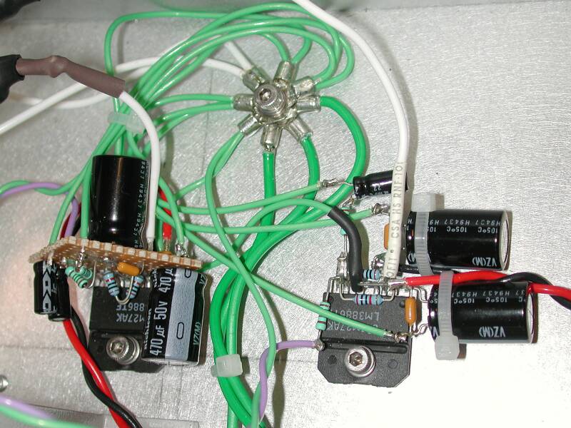
My amp was built using a schematic diagram pulled right off the NS data sheet, with the power supply added. Maybe the tweaking mentality about manufacturer supplied schematics comes from not understanding proper construction practices. One thing that is key to getting good performance from an LM3886 amplifier is to use proper grounding. Grounding isn't normally shown on a schematic diagram because it depends on the mechanical layout of the LM3886 amplifier circuit and chassis. Construction practices such as keeping high impedance circuits (such as amplifier inputs) away from components and wires carrying large currents (power transformer, power supply and LM3886 amplifier output wires) and using a "star" ground contribute more to high performance than $10 resistors and gold plated connectors. Click here for the schematic diagram showing the star ground
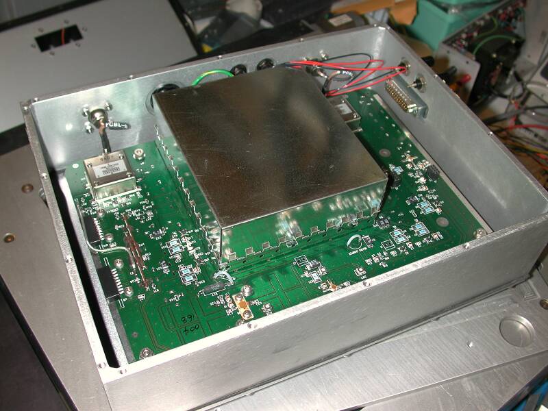
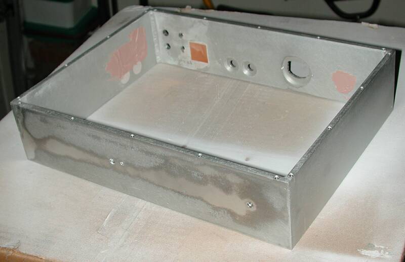
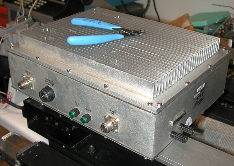
Usually, the housing is the most expensive part of the amp. It has to dissipate heat from the amp ICs and power transformer, it has to look acceptable, and it has to be large enough to hold everything. My amp's housing came from a scrap yard in Dallas where I was able to buy it for $1 per pound- about $15. The box originally housed a cell phone diversity antenna amplifier.
The side walls are 1/4" thick aluminum, welded at the corners, making this a super sturdy box that can dissipate a lot of heat. The top plate is 1/2" thick and is covered with fins to dissipate even more heat. The bottom plate, not shown, is 1/8" thick.
There were a bunch of connectors going through holes in the sides of the box. I was able to use some of them, but not others, so they were filled using Bondo auto body filler. First I taped some scraps of PCB material to the inside of the box then smeared the Bondo into the hole from the outside. After the Bondo hardened, I sanded the outside surface flush with the rest of the aluminum. It has worked out quite well and I recommend this technique to anyone who is recycling surplus enclosures.
I added a few more holes where I needed them, enlarged a couple of the existing holes, then applied the finish..
One of my other hobbies is restoring antique radios. I have one very special radio in my collection- a 1927 Neutrowound Super Six. This radio must have looked like it came from outer space back in 1927. At that time most radios were plain, rectangular wood boxes. This one was is a steel box with a very unusual look provided by the nickel plated tube covers that protrude through the top, and the exotic painted finish- cracked blue over orange!
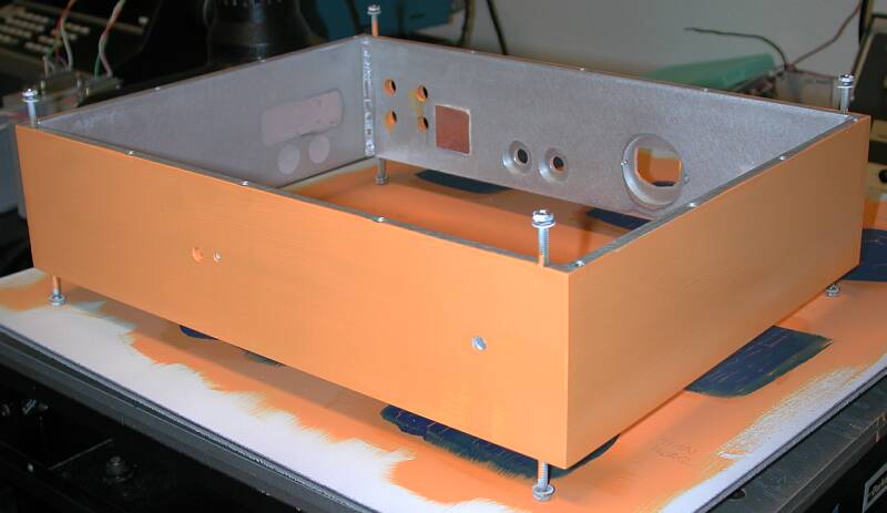
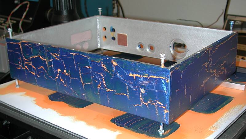
I like the finish on that radio a lot so I decided to try to duplicate it on my LM3886 amplifier. The radio was spray painted but I didn't have access to spray equipment so I had to use brushes to apply the finish. I selected a beautiful metallic blue (not quite the same as the radio) and a bright orange for the base coat. The result wasn't a very good match for the radio, but it came out sort of interesting anyway.
The finishing steps were primer, orange acrylic base coat, acrylic crackle medium, metallic blue acrylic, and finally an acrylic clear coat for protection.
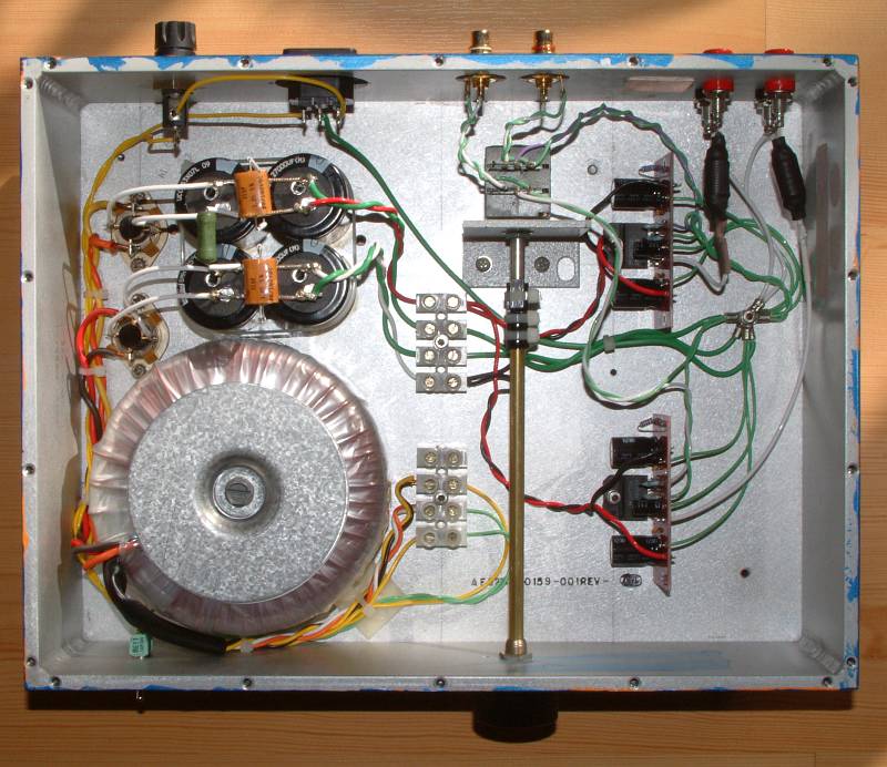
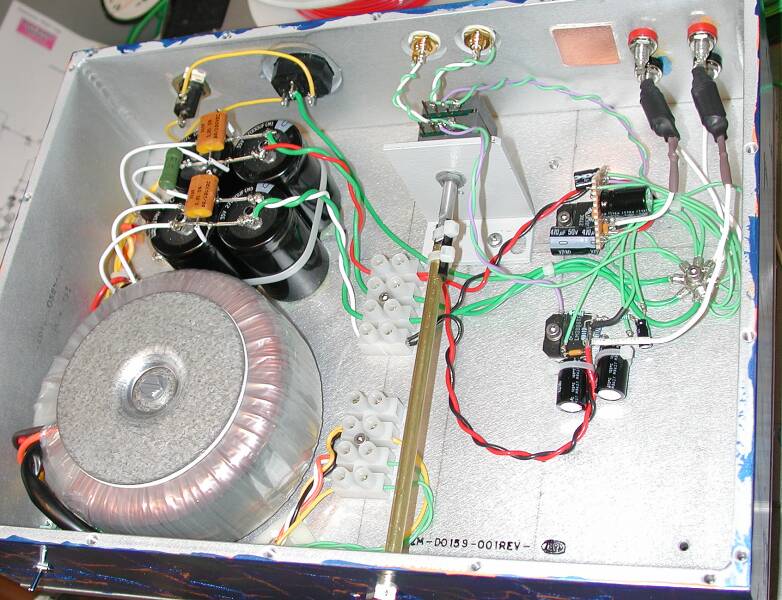
Next came construction of the LM3886 amplifier. The first channel was hay-wired because so few parts were required, but I didn't like the look of it much, so the second channel was built on perf board. The plan was to eventually go to printed circuit boards (more on that later). All grounds were brought to a single "star" point on the chassis to minimize the possibility of ground loops and asociated hum/noise.
The power transformer is a 320VA unit- a bit overkill since the amp can only deliver about 30 W per channel with the given power supply voltage.
The filter caps in the power supply total about 100,000 uF, more than enough, but at such a low voltage, capacitance is cheap ($6 total for the four caps), so why not?
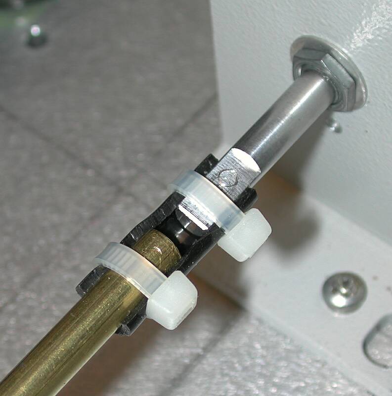
The volume control is mounted close to the input jacks on the rear panel to keep the signal wires short and far away from the power transformer. The shaft extension is a piece of 1/4" diameter brass tubing. Alignment of the volume control shaft and the front panel hole were not perfect so I made a flexible coupling from a piece of urethane air tubing and two tie-wraps. It works well- if you turn the knob past the stop in the pot, it slips a little, limiting the stress on the pot.
Shaft coupler
Eventually I got around to ordering some printed circuit boards and rebuilt the two LM3886 amplifier channels. I prefer PCBs because circuits that are hay-wired together may develop short circuits if wires have to be moved around to perform repairs .
Final interior with amp chips on printed circuit boards.
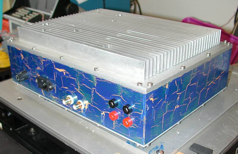
Back side of finished LM3886 amplifier
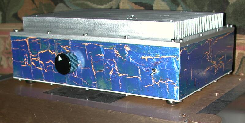
Front side of the finished LM3886 amplifier
LM3886 Amplifier Specs:
Weight: 18 lbs, 2 oz.
Size: 13" x 10" x 5"
Power transformer: 2x 18V @ 8.9A
Caps: 4x 27,000 uF @ 35V
Supply Voltage (no signal) +/- 26.5V
Volume control: ALPS dual 20K

Related Links
Downloads
LM3886 Amplifier - Link
|
|
|
| |
Accurate LC Meter
Build your own Accurate LC Meter (Capacitance Inductance Meter) and start making your own coils and inductors. This LC Meter allows to measure incredibly small inductances making it perfect tool for making all types of RF coils and inductors. LC Meter can measure inductances starting from 10nH - 1000nH, 1uH - 1000uH, 1mH - 100mH and capacitances from 0.1pF up to 900nF. The circuit includes an auto ranging as well as reset switch and produces very accurate and stable readings. |
|
PIC Volt Ampere Meter
Volt Ampere Meter measures voltage of 0-70V or 0-500V with 100mV resolution and current consumption 0-10A or more with 10mA resolution. The meter is a perfect addition to any power supply, battery chargers and other electronic projects where voltage and current must be monitored. The meter uses PIC16F876A microcontroller with 16x2 backlighted LCD. |
|
|
|
60MHz Frequency Meter / Counter
Frequency Meter / Counter measures frequency from 10Hz to 60MHz with 10Hz resolution. It is a very useful bench test equipment for testing and finding out the frequency of various devices with unknown frequency such as oscillators, radio receivers, transmitters, function generators, crystals, etc. |
|
1Hz - 2MHz XR2206 Function Generator
1Hz - 2MHz XR2206 Function Generator produces high quality sine, square and triangle waveforms of high-stability and accuracy. The output waveforms can be both amplitude and frequency modulated. Output of 1Hz - 2MHz XR2206 Function Generator can be connected directly to 60MHz Counter for setting precise frequency output. |
|
|
|
BA1404 HI-FI Stereo FM Transmitter
Be "On Air" with your own radio station! BA1404 HI-FI Stereo FM Transmitter broadcasts high quality stereo signal in 88MHz - 108MHz FM band. It can be connected to any type of stereo audio source such as iPod, Computer, Laptop, CD Player, Walkman, Television, Satellite Receiver, Tape Deck or other stereo system to transmit stereo sound with excellent clarity throughout your home, office, yard or camp ground. |
|
USB IO Board
USB IO Board is a tiny spectacular little development board / parallel port replacement featuring PIC18F2455/PIC18F2550 microcontroller. USB IO Board is compatible with Windows / Mac OSX / Linux computers. When attached to Windows IO board will show up as RS232 COM port. You can control 16 individual microcontroller I/O pins by sending simple serial commands. USB IO Board is self-powered by USB port and can provide up to 500mA for electronic projects. USB IO Board is breadboard compatible. |
|
|
|
|
ESR Meter / Capacitance / Inductance / Transistor Tester Kit
ESR Meter kit is an amazing multimeter that measures ESR values, capacitance (100pF - 20,000uF), inductance, resistance (0.1 Ohm - 20 MOhm), tests many different types of transistors such as NPN, PNP, FETs, MOSFETs, Thyristors, SCRs, Triacs and many types of diodes. It also analyzes transistor's characteristics such as voltage and gain. It is an irreplaceable tool for troubleshooting and repairing electronic equipment by determining performance and health of electrolytic capacitors. Unlike other ESR Meters that only measure ESR value this one measures capacitor's ESR value as well as its capacitance all at the same time. |
|
Audiophile Headphone Amplifier Kit
Audiophile headphone amplifier kit includes high quality audio grade components such as Burr Brown OPA2134 opamp, ALPS volume control potentiometer, Ti TLE2426 rail splitter, Ultra-Low ESR 220uF/25V Panasonic FM filtering capacitors, High quality WIMA input and decoupling capacitors and Vishay Dale resistors. 8-DIP machined IC socket allows to swap OPA2134 with many other dual opamp chips such as OPA2132, OPA2227, OPA2228, dual OPA132, OPA627, etc. Headphone amplifier is small enough to fit in Altoids tin box, and thanks to low power consumption may be supplied from a single 9V battery. |
|
|
|
|
|
Arduino Prototype Kit
Arduino Prototype is a spectacular development board fully compatible with Arduino Pro. It's breadboard compatible so it can be plugged into a breadboard for quick prototyping, and it has VCC & GND power pins available on both sides of PCB. It's small, power efficient, yet customizable through onboard 2 x 7 perfboard that can be used for connecting various sensors and connectors. Arduino Prototype uses all standard through-hole components for easy construction, two of which are hidden underneath IC socket. Board features 28-PIN DIP IC socket, user replaceable ATmega328 microcontroller flashed with Arduino bootloader, 16MHz crystal resonator and a reset switch. It has 14 digital input/output pins (0-13) of which 6 can be used as PWM outputs and 6 analog inputs (A0-A5). Arduino sketches are uploaded through any USB-Serial adapter connected to 6-PIN ICSP female header. Board is supplied by 2-5V voltage and may be powered by a battery such as Lithium Ion cell, two AA cells, external power supply or USB power adapter. |
|
200m 4-Channel 433MHz Wireless RF Remote Control
Having the ability to control various appliances inside or outside of your house wirelessly is a huge convenience, and can make your life much easier and fun. RF remote control provides long range of up to 200m / 650ft and can find many uses for controlling different devices, and it works even through the walls. You can control lights, fans, AC system, computer, printer, amplifier, robots, garage door, security systems, motor-driven curtains, motorized window blinds, door locks, sprinklers, motorized projection screens and anything else you can think of. |
|
|
|