| |
This is a scaled-down version of Nelson Pass' Zen power amplifier for my headphones. For this use, the Zen topology is perfect excellent sound quality, simplicity, linearity and no multi-stage feedback. It is a single stage class A MOSFET design with the right gain and a low output impedance. Here we don't have the limitations of the Zen amps at least in the single-stage implementations regarding speaker compatibility. A single stage topology with correct interfacing values misses very few things in the original music message.
The gain device in the original Zen amplifier is biased by fixed current source. For this amp, I employed an active current source described in Pass' patent no. 5,710,522 (see Zen Variations Part 2). The benefits of an active source include higher output current, lower distortion and 50% theoretical operating efficiency (compared to the 25% efficiency from a fixed source). This type of current source is featured in the Aleph power amplifiers from Pass Labs.
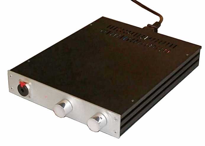
I designed this circuit to obtain the best sound from my Grado SR-325 headphones. Portability here was not imperative, so the high power consumption of a real class A amp was not a big drawback. I developed this project at the beginning of 2002 and it was first presented at DIYaudio.com in February 2002. Since the intellectual property belongs to Pass Labs, this circuit is intended only for not–for–profit use, unless the current source topology is altered. I wish to thank Nelson Pass for his open-mindedness and involvement in the DIY audio world; the DIYer community will be always grateful to him!
THE CIRCUITS
The Amplifier
Schematic for Zen headphone amplifier - one channel
Figure 1
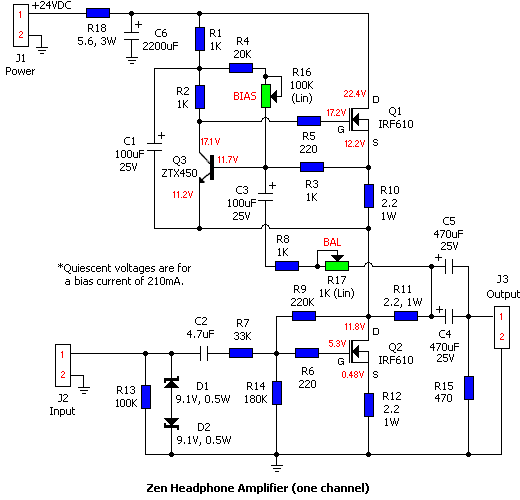
The schematic in figure 1 shows one channel of the headphone amp. The HexFets employed are the usual International Rectifier IRF610, both for the active side and for the current source. The circuit is quite simple, only one gain stage built around an IRF610 (Q2 at the bottom of the schematic), biased by another IRF610 (Q1). The two diodes (D1 and D2) are for over-voltage protection purposes: any type, between few volts and about 15-16V will work fine.
The main idea behind Pass' variable current source is that the bias current is controlled by the output signal. The "sensing amplifier" is built around Q3. An output resistor, R11, senses the current through the load. Q3 drives the gate of Q1 and modulates the bias current in Q2 according to the "sensed" load current.
The Grados are low impedance headphones, about 30 ohms, and are very efficient too. To get the maximum output swing required by a headphone amplifier, I measured, by a storage scope, the maximum output level at which the headphones began obviously to distort. At 2.7Vpeak (1.9Vrms), there was enormous sound pressure from the headphones. This was definitely plentiful!
To obtain the wide compatibility with low-output sources, such as tape decks and tuners, I chose at least 10dB gain for the amplifier. This ensures adequate headroom with almost every CD and CD player I've tried. The amplifier's output current depends on the the output stage bias current, which can be set between a few mA and about 280mA. If you have an high-impedance headphone, you don’t need to charge the higher current setup, even if at least 100mA bias current is advisable for the best sound quality.
This circuit makes use of feedback, but mainly to estabilish the working point, since the open-loop performance is quite good. R12 forms a little local feedback. It slightly enhances the circuit linearity, without further dropping the input impedance of the stage.
The main feedback network (R7, R9, R14) takes care of the operating parameters of the circuit, such as working point, gain, bandpass width and, in consequence, input impedance. It has been arranged for a power supply rail of about 24V and for an input impedance of about 35K Ohms (above a good part of the audio spectrum). With those values, the upper frequency limit of the amplifier is about 20KHz (-3dB) and the mid-band gain about 13dB (equivalent to a voltage gain of 4.5).
Changing the gain of the amp is not difficult, if you know what you're doing. Although the gain is controlled by local feedback network (R7, R9 and R14), changing these values will change the frequency response, and the input impedance too. You must consider all the parameters that change with it. However, for me, this configuration is, at the moment, the best configuration among all for the gain.
If you want to widen the passband, you may change some of the feedback resistors. For example, if R7 is 10K Ohm, R14 is 53K Ohm and R9 68K Ohm, the input impedance now drops down to about 11K Ohm, but the "-3dB" upper frequency limit goes up to about 60-80KHz, at least according to simulations. Anyway, with Grado headphones (I’ve tried with the latest RS-1, SR-325 and SR-80) the passband limitation is not a flaw at all; these phones are quite bright.
R17 (the "Balance" trimmer) is useful to make equal the signal currents (not bias current!) between the HexFets' drains, where the performance of the active current source is optimal. Thus, setting R17 (described later) requires a signal generator and an AC voltmeter and/or an oscilloscope.
R16 sets the bias current, between few mAs and about 300mA. Although the current sensing system decides how to vary bias current according to the needs of the load, the quiescent bias current must be set manually. The amplifier can deliver about twice the bias current to the load due to the operation of the active current source: Iout = 2 * Ibias. A bias current of 300mA is plentiful, enough for the destruction of the Grado headphones, probably the lowest impedance headphones for high quality listening.
The output impedance of the amplifier is affected by the bias current. Here a classical negative feedback loop doesn't help. The output impedance decreases as the bias current increases. This should not give any cause for concern. With greater bias current, the output peak current increases too (see above), and the distortion goes down, with the same load at the output. For example, with a bias current of 300mA, the output impedance is about 18 Ohms; the output impedance is 25 Ohms with a bias current of 100mA.
Timer and Equalizer
Schematic for output muting timer and equalizer.
Figure 2
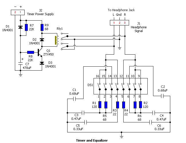
The muting timer and equalizer circuits are optional, but highly recommended - especially the muting timer. A timer-controlled relay short-circuits (mutes) the outputs (a couple of seconds are plentiful) to avoid the power-on bump. It employs a normally-closed 12V relay that short-circuits the amp outputs to GND. After about 2 seconds, the relay turns on, and the outputs of the amp are "free". When the amp is turned off (opening the switch's contacts connected to the J3 poles in the power supply board), the timer capacitor (C7) completes its discharge in few tenths of second, mainly by the R4 resistor, to short-circuit the amp's outputs before the power-off bump.
With Grados, I employ a simple equalizer to slightly shave the upper frequency behaviour, so the sibilances are not so noticeable. The magnitude of these modifications is about one dB or so. The effect can be tuned by four dip-switches per channel, located in the bottom of the chassis. These switches put an RC filter in parallel with the headphone transducer; this, combined with the amplifier output impedance, make the wanted correction. The cut-off frequencies are not so important, since these filters don't work as crossovers do, but they slightly tame the upper frequency behaviour. Furthermore, they work together, not separately from each other.
Power Supply
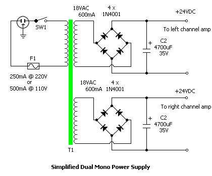
Schematic for power supply - version 1.
Figure 3
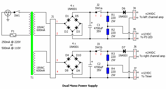
There are two power supplies: one version for the amplifier and muting timer (figure 3) and a simplified version for the amplifier only (figure 4). The power transformer secondary supplies about 18Vrms, so the V+ rail is about 24VDC, adequate also for hi-Z headphones. I don’t like regulated power supply units for this kind of circuits, so a simple Pi filter is employed here, made by C2, C6 and R18. The PSRR of the audio circuit is about 30dB. With a 30-Ohm output load, I’ve measured about 350uV (1uV = 1*10-6 Volts!!); in spite of this, since the Grados are quite sensitive headphones, a little hum can be heard, only if the room noise floor is absolutely low and there is no signal applied at the input, of course.
Schematic for power supply - version 2.
Figure 4
The timer circuit is feed by the +/- TIMER plugs in the power supply board, obtained by a resistor partition from the 24VDC rail. The values are calcuated for a fast discharge of the timer capacitance (few tens of milliseconds), so the power-off bump is cut by this circuit. On the other hand, the power dissipation of the two resistors, R3 and R4 (timer), is not so moderate. They get hot, so at least 3W components must be employed. For symmetry purposes, the other channel power supply also employs two resistors (R1 and R2), which can feed a 12V LED assembly (with the resistor integrated in the LED's mounting hardware).
In the first power supply, diodes D6 and D7 prevent the reverse discharge of the second big capacitor of the PI filter of the power supply (C6 shown in amplifier schematic - figure 1). D7 also prevents a delay in the relay switching at power-off, by keeping C7 and C6 electrically separate. Otherwise, C7 and C6 are effectively in parallel, which slows the discharge of C7. In this latter case, the timer closes the relay connected to the amp outputs after the power-off bump happens, and that is not so useful.
CONSTRUCTION
Download PC Board Layouts for Zen Headphone Amp (237K)
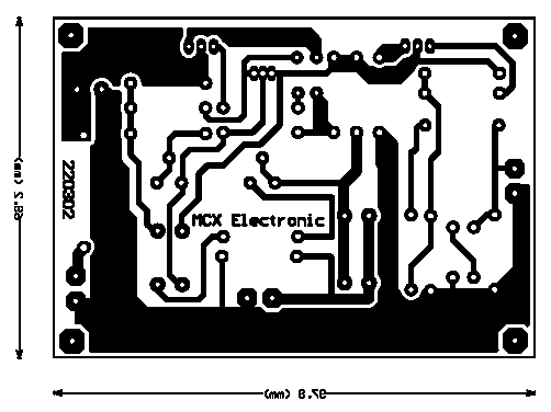
In addition to the amplifier PC boards, I built boards for the power supply (shown above at the rear of the chassis) and the timer-equalizer circuit (click the link above to download the patterns and overlays in PDF format). Included in the zip file are two drawings showing how to wire both signal and power connections. They are called power_connections.pdf and signal_connections.pdf.
As often happens with simple circuits, the amplifier is quite sensitive to component quality. Q1 and Q2 are critical. If you decide to employ other devices, you must make sure that the input gate capacitance is not excessive. The high frequency roll-off depends mainly on this parameter. With IRF520, 530 and 620, the frequency response is not acceptable. The only device that seems to work well is the IRF 610 - at least that I could find on the market.
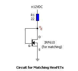
Circuit for matching HexFETs.
Figure 5
The "active side" HexFETs (Q2) must be matched to ensure the same gain between the two channels (the current source gain can be set by the trimmer (this is another difference respect to the current sources in the Aleph amps, which constrain to select all the devices, not only the "signal" ones).
I built a simple matching circuit shown in figure 5. The bias current is 360mA (calculated as Ibias = (V1 - 4)/R1). It may be regulated with a correct value for the power supply voltage (12V in this case) and for the R value. The HexFET component should be thermal stabilized (a couple of minutes or so) and heatsinked during this test. The selection parameter is Vd, and its value is around 4V. For matching the HexFETs, I think that 0.1V tolerance is plentiful. Devices matched to a few fractions of volt can be achieved, in my opinion, by buying ten or fifteen pieces, and make the matching among these. I bought 50 pieces and found, if I recall right, many 4.17V units.
I used ZTX450s because I had some of these in my pocket. To substitute for the ZTX450, any NPN transistor with an hfe greater than 100 will work well. With the values as in the schematic diagram, the Q3 collector current is about 2.5mA and the Vce drop about 5V. Figure 1 shows the quiescent voltages (taken with reference to ground) of the active semiconductors when the amp is set with 210mA bias current. These should be sufficient for troubleshooting purposes.
C3, C4 and C5 should be high quality electrolytic capacitors. ELNA Starget, Cerafine, and Rubycon Black Gate are perfect for this use. Good quality electrolytic capacitors are needed here: far better than bypassing bad – or old - electrolytic stuff by plastic film types. I totally agree with Richard Murdey's opinions about bypass practice.
The C2 (4.7uF) and C4, C5 (470uF) values are non-critical and a little plentiful. You can modify their values without any low-frequency loss. I could find only good quality 470uF (or less) components (Elna Starget stuff) here in Italy. If you want to simplify, a single 470uF piece for C4 or C5 will work fine. With 940uF (or 2 x 470uF), the lower cutoff frequency is about 4Hz with a 32 Ohm load. If the total capacitance were 470uF, the Fc should be double (8Hz), of course.
I employed 0.5W resistors for the whole amp, except for R10, R11 and R12, where I used 1W stuff. I like to oversize the power ratings to otain colder devices and smaller thermal noise, but this is only a personal opinion. In the power supply board, all of the resistors must be 3W: remember that the power dissipation is quite high!
A suitable heat sink, or a metal chassis, for the power HexFets must be employed. To dissipate the not marginal heat quantity from the power HexFETs – about 3.5 watts each, the bottom of my chassis is made of black-anodized aluminum alloy. The TO-220 cases have been insulated from the chassis with Sil-Pad sheets (a substitute for silicone grease - I hate silicone grease) and plastic bolts.
A 100 Ohm resistor is connected between the common ground of the two channels and the chassis, to ensure a shielding function.
Interior of Zen headphone amplifier chassis.
The timer and the high frequency equalizer are placed on the same board. The timer circuit provides a 2-second output muting. The J1 connector from this circuit must be connected in parallel with the headphone jack, so no relay resistance is seen by the signal path. The equalizer slightly tames the behaviour of the upper frequencies, and is a convenient feature for certain headphones, like my Grado SR-325. DS1, an 8-pole DIP-switch (4 switches per channel), which can be seen on the bottom of the chassis, controls the intensity of the equalizer's action.
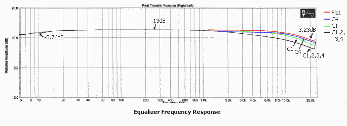
Frequency response of equalizer.
Figure 6
The DIP switch layout is symmetrical. The left-hand 4 poles are for left channels, the others for the right channel, of course. Switches 4 and 5 control the upper treble, switches 1 and 8 permit a soft mid-high control, switches 2 and 7 enhance this intervention, and switches 3 and 6 lower the frequency from which the correction begins. For the values of the RC network, you can see the schematic in figure 2.
The "L-folded" aluminum sheet is employed to shield any possible magnetic loss from the transformer and to fasten the power-on switch too. The power-on switch is a double-pole component (a rotary switch). It must be connected to SWITCH1A (J2) and SWITCH1B (J3) connectors on the power supply board. The power supply primary winding is always connected to the mains. The headphone amps should be connected to the "+/- RIGHT CHANNEL" and "+/- LEFT CHANNEL" plugs.
The power transformer is a good quality 50VA toroidal type, although 30VA is well enough. In Europe we have 220-230 VAC, In USA I think there are 110-115 VAC, so the fuse current rating for the American builders should be twice than the European standard. I've not measured the current inrush of the power supply, bu 250mA rating for the Europeans, and 500mA for the Americans ("T" fuse, or delayed type, of course) should be a correct choice. Its purpose is only to avoid a disaster, if there were a power transformer failure.
The enclosure I used is made of aluminium alloy, except for the top cover, which is made of steel. Dimensions: 230 x 42 x 287 millimeters. The bottom was originally identical to the top. I made it from a 2mm-thick aluminium sheet for heat dissipation purposes: the hexfets must be screwed to this. The enclosure is made by "Electronica 2000", an Italian cabinets manufacturer for electronic DIY projects.
The left knob on the chassis is the volume potentiometer. It is a high-quality 40mm Alps RK-40 (20K Ohm x 2 ) logarithmic potentiometer; the other is the power-on rotary switch. The whole signal wiring is made by silver OFC – with Teflon insulation – wire. For the inputs, I used gold-plated Teflon insulated RCA connectors (mounted on the rear). The headphone jack is an high-quality Neutrik piece, with a lock mechanism. I bought it from RS Components (about 7-8 EUROs).
MEASUREMENTS
All measurements have been done with HP and Tektronix instruments, and with Sound Technology Spectralab 4.32 demo version, especially for printing convenience.
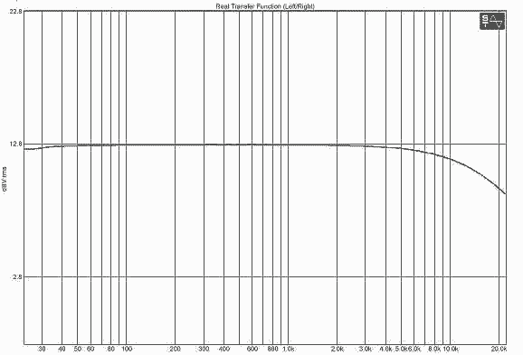
Frequency response of the amplifier: headphone load 33 Ohm resistive. The upper –3dB point is about 20KHz, the lower limit is below 4Hz.
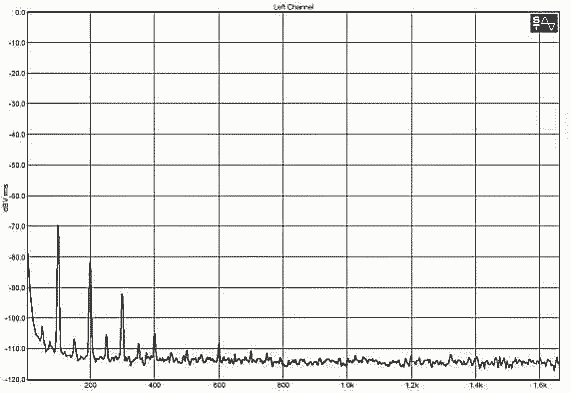
Power supply noise, measured at the output of the amplifier, with no signal at the input. Headphone load 33 Ohm resistive. The 100Hz peak is about –70dBVrms, or about 416uVrms, the 2nd and 3rd order harmonics are quite below this level (-82 dBVrms and –92 dBVrms respectively). No signal at the input, of course.
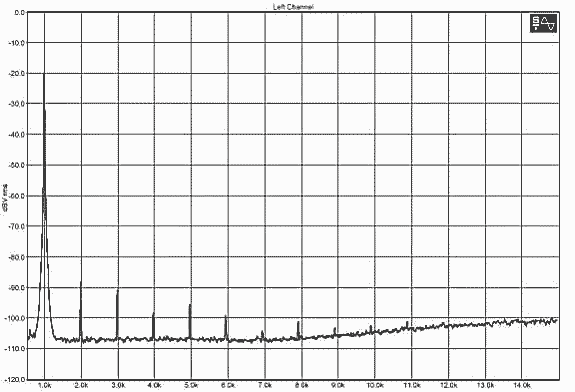
Spectrum analysis: output level 100mVrms on 33 Ohm load, 1KHz. THD+N is about 0.059% according to Spectralab, about 0.08% according to the HP distortion analyzer. Below –100dBV also the soundcard’s distortion appears, the highest order harmonics are typical of this setup. The 100Hz distortion is quite lower – about 0.03%, not so the 10KHz: at this frequency, we have about 0.18%: these measurement were made with my Hewlett Packard Distortion Analyzer. The spectrum shape, anyway, is almost the same, as I could see with a wideband L.F. Spectrum Analyzer.
Same as above, but with 500mVrms, 1KHz. Spectralab THD+N: 0.20%, HP D. A. 0.19%.
With HP D. A.:
100Hz: 0.09%.
10KHz: 1.1%
Now the output level is about 1Vrms, 1KHz as usual. Spectralab THD+N: 0.40%, HP D. A. 0.40%.
With HP D. A.:
100Hz: 0.18%.
10KHz: 2.2%
In spite of the high output level, the distortion’s benign shape is preserved. The maximum output level is about 3.3Vrms, always with 33 Ohm load. With higher impedance loads, the distortion level decreases accordingly. The spectrum distortion shape, and the frequency-distortion behaviour are typical of this kind of (simple single-ended) circuits. This is the cost to count for a single-stage structure: on the other hand the sound is beautiful.
FINAL SETUP AND RESULTS
Setting R16 (bias trimmer): I chose a bias current of about 210mA; with higher impedance headphones a lighter bias will be fine. Anyway, I'd set the bias current between 100 and 300mA, not less, even with higher impedance headphones. More is not useful.
To measure the bias current, connect a DC voltmeter, without any input signal, across R10 or R12 (preferably R12 because its cold side is connected to ground). The resistance value is 2.2 Ohms, so the bias current is about V(R12)/2.2 [Amperes]. For example, with 0.6VDC across R12, we obtain 0.6/2.2=0.27A, or 270mA.
Setting R17 (balance trimmer): You must use a signal generator and an AC voltmeter and/or an oscilloscope. To trim the Id(Q1)/Id(Q2) ratio, apply a test signal at the input – for example 1KHz - and measure the AC contribution across R10 and R12. Adjust R17 so that the contribution across each resistor is equal. You can try to vary this value while you're listening to the amp, and see for yourself the best setting.
Setting the EQ: The frequency responses of the equalizer DIP switch settings are shown in figure 6. Switches 1, 2 and 3 (or switches 8, 7 and 6 for the other channel) refer to the same RC network. They work in conjunction with each other. Going from a light to strong effect, the switches are set as follows: S1, S2, S1+S2. S3 is used to lower the frequency from which the correction begins.
S4 is the lightest correction of the top end of the spectrum. Consider that with the Grado SR-325 headphones, I always use the S4 correction. With bad recordings, sometimes I employ the S1 setup. The other EQ settings are quite "heavy" for my tastes. With a friend's Grado RS-1, no correction was needed, for the most of listenings.
I have a Grado RA-1 headphone amp, and I have owned a QED headphone amp too (the QED is not a good sounding amp at all, at least in my opinion). With respect to my RA-1 amp, all my records do sound better through the Zen amp. Bad recordings sound better, good recordings much more better. The sound seems more natural in the whole spectrum, more dynamic, and the soundstage is much more open, large. The only critical point I hear with bad-recorded stuff, is the high portion of the spectrum, but this is the Grado SR-325 problem: in this case, the RA-1 is quite unlistenable, really. The RC equalizer tames this "Grado 325" effect.
The opinion of friends of mine who have listened to the amplifiers is that the Zen amp is more open, detailed and less fatiguing than the Grado RA-1. The transients are more natural and effortless - no compression. I designed the Zen amp just for Grado cans. I've tried it with my SR-325 cans, with a friend's RS-1 and SR-80. The circuit is optimized to work with Grado products, but I’ve tried it also with an old AKG 141 Monitor, and a couple of Sennheisers, and the sound was good too. Maybe, with these transducers, it would be advisable to configure the Zen amp with the "wider band" setup. Feel free to contact me at the email address below. As time permits, I'll be glad to answer to your questions.

Related Links
Downloads
Zen Headphone Amplifier - Link
|
|
|
| |
Accurate LC Meter
Build your own Accurate LC Meter (Capacitance Inductance Meter) and start making your own coils and inductors. This LC Meter allows to measure incredibly small inductances making it perfect tool for making all types of RF coils and inductors. LC Meter can measure inductances starting from 10nH - 1000nH, 1uH - 1000uH, 1mH - 100mH and capacitances from 0.1pF up to 900nF. The circuit includes an auto ranging as well as reset switch and produces very accurate and stable readings. |
|
PIC Volt Ampere Meter
Volt Ampere Meter measures voltage of 0-70V or 0-500V with 100mV resolution and current consumption 0-10A or more with 10mA resolution. The meter is a perfect addition to any power supply, battery chargers and other electronic projects where voltage and current must be monitored. The meter uses PIC16F876A microcontroller with 16x2 backlighted LCD. |
|
|
|
60MHz Frequency Meter / Counter
Frequency Meter / Counter measures frequency from 10Hz to 60MHz with 10Hz resolution. It is a very useful bench test equipment for testing and finding out the frequency of various devices with unknown frequency such as oscillators, radio receivers, transmitters, function generators, crystals, etc. |
|
1Hz - 2MHz XR2206 Function Generator
1Hz - 2MHz XR2206 Function Generator produces high quality sine, square and triangle waveforms of high-stability and accuracy. The output waveforms can be both amplitude and frequency modulated. Output of 1Hz - 2MHz XR2206 Function Generator can be connected directly to 60MHz Counter for setting precise frequency output. |
|
|
|
BA1404 HI-FI Stereo FM Transmitter
Be "On Air" with your own radio station! BA1404 HI-FI Stereo FM Transmitter broadcasts high quality stereo signal in 88MHz - 108MHz FM band. It can be connected to any type of stereo audio source such as iPod, Computer, Laptop, CD Player, Walkman, Television, Satellite Receiver, Tape Deck or other stereo system to transmit stereo sound with excellent clarity throughout your home, office, yard or camp ground. |
|
USB IO Board
USB IO Board is a tiny spectacular little development board / parallel port replacement featuring PIC18F2455/PIC18F2550 microcontroller. USB IO Board is compatible with Windows / Mac OSX / Linux computers. When attached to Windows IO board will show up as RS232 COM port. You can control 16 individual microcontroller I/O pins by sending simple serial commands. USB IO Board is self-powered by USB port and can provide up to 500mA for electronic projects. USB IO Board is breadboard compatible. |
|
|
|
|
ESR Meter / Capacitance / Inductance / Transistor Tester Kit
ESR Meter kit is an amazing multimeter that measures ESR values, capacitance (100pF - 20,000uF), inductance, resistance (0.1 Ohm - 20 MOhm), tests many different types of transistors such as NPN, PNP, FETs, MOSFETs, Thyristors, SCRs, Triacs and many types of diodes. It also analyzes transistor's characteristics such as voltage and gain. It is an irreplaceable tool for troubleshooting and repairing electronic equipment by determining performance and health of electrolytic capacitors. Unlike other ESR Meters that only measure ESR value this one measures capacitor's ESR value as well as its capacitance all at the same time. |
|
Audiophile Headphone Amplifier Kit
Audiophile headphone amplifier kit includes high quality audio grade components such as Burr Brown OPA2134 opamp, ALPS volume control potentiometer, Ti TLE2426 rail splitter, Ultra-Low ESR 220uF/25V Panasonic FM filtering capacitors, High quality WIMA input and decoupling capacitors and Vishay Dale resistors. 8-DIP machined IC socket allows to swap OPA2134 with many other dual opamp chips such as OPA2132, OPA2227, OPA2228, dual OPA132, OPA627, etc. Headphone amplifier is small enough to fit in Altoids tin box, and thanks to low power consumption may be supplied from a single 9V battery. |
|
|
|
|
|
Arduino Prototype Kit
Arduino Prototype is a spectacular development board fully compatible with Arduino Pro. It's breadboard compatible so it can be plugged into a breadboard for quick prototyping, and it has VCC & GND power pins available on both sides of PCB. It's small, power efficient, yet customizable through onboard 2 x 7 perfboard that can be used for connecting various sensors and connectors. Arduino Prototype uses all standard through-hole components for easy construction, two of which are hidden underneath IC socket. Board features 28-PIN DIP IC socket, user replaceable ATmega328 microcontroller flashed with Arduino bootloader, 16MHz crystal resonator and a reset switch. It has 14 digital input/output pins (0-13) of which 6 can be used as PWM outputs and 6 analog inputs (A0-A5). Arduino sketches are uploaded through any USB-Serial adapter connected to 6-PIN ICSP female header. Board is supplied by 2-5V voltage and may be powered by a battery such as Lithium Ion cell, two AA cells, external power supply or USB power adapter. |
|
200m 4-Channel 433MHz Wireless RF Remote Control
Having the ability to control various appliances inside or outside of your house wirelessly is a huge convenience, and can make your life much easier and fun. RF remote control provides long range of up to 200m / 650ft and can find many uses for controlling different devices, and it works even through the walls. You can control lights, fans, AC system, computer, printer, amplifier, robots, garage door, security systems, motor-driven curtains, motorized window blinds, door locks, sprinklers, motorized projection screens and anything else you can think of. |
|
|
|