| |
Most transmitter has several variable capacitors which are used to match impedance for transistors and antennas. I know people hate trimmers and so did I. The reason is that it is difficult to trim a system if you can't measure the performances.
To trim a transmitter you need to measure the output power.
Most transmitter are tuned with a dummy load of 50 ohm to substitute an antenna of 50 ohm.
Not everyone has a power meter, and how can you know that the antenna you connect is purely 50 ohm.
If not, the hole trimming is waste of time!
What you would like to do is to measure the radiated power out from the antenna you actually are going to use.
If you can measure the radiated energy field you can easy tune the system for max output field strength (max power).
So, how can we measure the radiated energy field?
The block diagram at right show you one easy way to measure the RF filed strength. To the left you find a dipole antenna.
The antenna should be cut to match the receiving frequency ...
The length of antenna is not a critical at all.
Length = 0.95*300/(4*freq) <= (freq = Mhz)
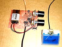
The RF signal is then rectified in a diode and the DC voltage is then amplified in an OP-amplifier. To display the voltage I use a panel meter. The amplifier gain can be set with a potentiometer and I have also added a bias voltage to set the zero level of panel meter.
This unit will not show you the exact power like a power meter, but it will show you the relative power transmitted out from your transmitter and antenna. The panel meter is connected to the PCB with 5 meter long wire.
In this way I can put the field-meter 5m away from where I am and still be able to watch the panel meter.
I will tell you how I use my filed meter.
I place the RF field meter 5 meter away from my transmitter.
I then put all variable capacitor to middle.
I switch on the transmitter and go to my RF filed meter. I then set the gain (with potentiometer) so I get half of max reading on the panel meter. I then switch off the transmitter and set the offset (with other potentiometer) so I get zero reading on the panel meter.
I repeat this tuning process unit it looks good.
Now I can start tuning the transmitter and watch the panel meter.
All I need to do is to tune for max reading on the panel meter. Then I know the RF field is at max strength.
I also advice you too receive the signal you are transmitting to check that it sound good.
I also check the current to the transmitter so it don't get to high.
Usually the current go down when good tuning has been done and you got max power.
Another good thing to monitor is the temperature of the transistors.
Don't let them go to hot.
I find my RF field meter to be a very simple and powerful too.
This RF filed meter works from 30mW to several watt.
Hardware and schematic
Click to open in new window Please look at the schematic to follow my function description.
At the bottom left corner you will see a voltage divider. This divider is to produce a virtual ground of 4.5VDC. Above you will find the dipole antenna.
The dipole antenna will pick up some radiated energy and the diode will rectify the RF signal to a DC voltage at VRF. This voltage is still quit low and needs to be amplified before it can control the panel meter.
The signal then enter the OP which amplifies the voltage to suitable level set by the "Gain" potentiometers". The second OP acts as a voltage follower and set the offset (zero) for the panel meter.
The panel meter is connected to the board via two wires (5meter long).
To prevent any RF signal to be induced in this long wire I have added 2 ferrite block which will act as high impedance units.
You can use any ferrite block or large inductor (10uH).
Final word
This little unit has helped me so much to tuner my transmitter.
Easy to build and to use.
Related Links
Downloads
RF Field Strength Meter - Link
|
|
|
| |
Accurate LC Meter
Build your own Accurate LC Meter (Capacitance Inductance Meter) and start making your own coils and inductors. This LC Meter allows to measure incredibly small inductances making it perfect tool for making all types of RF coils and inductors. LC Meter can measure inductances starting from 10nH - 1000nH, 1uH - 1000uH, 1mH - 100mH and capacitances from 0.1pF up to 900nF. The circuit includes an auto ranging as well as reset switch and produces very accurate and stable readings. |
|
PIC Volt Ampere Meter
Volt Ampere Meter measures voltage of 0-70V or 0-500V with 100mV resolution and current consumption 0-10A or more with 10mA resolution. The meter is a perfect addition to any power supply, battery chargers and other electronic projects where voltage and current must be monitored. The meter uses PIC16F876A microcontroller with 16x2 backlighted LCD. |
|
|
|
60MHz Frequency Meter / Counter
Frequency Meter / Counter measures frequency from 10Hz to 60MHz with 10Hz resolution. It is a very useful bench test equipment for testing and finding out the frequency of various devices with unknown frequency such as oscillators, radio receivers, transmitters, function generators, crystals, etc. |
|
1Hz - 2MHz XR2206 Function Generator
1Hz - 2MHz XR2206 Function Generator produces high quality sine, square and triangle waveforms of high-stability and accuracy. The output waveforms can be both amplitude and frequency modulated. Output of 1Hz - 2MHz XR2206 Function Generator can be connected directly to 60MHz Counter for setting precise frequency output. |
|
|
|
BA1404 HI-FI Stereo FM Transmitter
Be "On Air" with your own radio station! BA1404 HI-FI Stereo FM Transmitter broadcasts high quality stereo signal in 88MHz - 108MHz FM band. It can be connected to any type of stereo audio source such as iPod, Computer, Laptop, CD Player, Walkman, Television, Satellite Receiver, Tape Deck or other stereo system to transmit stereo sound with excellent clarity throughout your home, office, yard or camp ground. |
|
USB IO Board
USB IO Board is a tiny spectacular little development board / parallel port replacement featuring PIC18F2455/PIC18F2550 microcontroller. USB IO Board is compatible with Windows / Mac OSX / Linux computers. When attached to Windows IO board will show up as RS232 COM port. You can control 16 individual microcontroller I/O pins by sending simple serial commands. USB IO Board is self-powered by USB port and can provide up to 500mA for electronic projects. USB IO Board is breadboard compatible. |
|
|
|
|
ESR Meter / Capacitance / Inductance / Transistor Tester Kit
ESR Meter kit is an amazing multimeter that measures ESR values, capacitance (100pF - 20,000uF), inductance, resistance (0.1 Ohm - 20 MOhm), tests many different types of transistors such as NPN, PNP, FETs, MOSFETs, Thyristors, SCRs, Triacs and many types of diodes. It also analyzes transistor's characteristics such as voltage and gain. It is an irreplaceable tool for troubleshooting and repairing electronic equipment by determining performance and health of electrolytic capacitors. Unlike other ESR Meters that only measure ESR value this one measures capacitor's ESR value as well as its capacitance all at the same time. |
|
Audiophile Headphone Amplifier Kit
Audiophile headphone amplifier kit includes high quality audio grade components such as Burr Brown OPA2134 opamp, ALPS volume control potentiometer, Ti TLE2426 rail splitter, Ultra-Low ESR 220uF/25V Panasonic FM filtering capacitors, High quality WIMA input and decoupling capacitors and Vishay Dale resistors. 8-DIP machined IC socket allows to swap OPA2134 with many other dual opamp chips such as OPA2132, OPA2227, OPA2228, dual OPA132, OPA627, etc. Headphone amplifier is small enough to fit in Altoids tin box, and thanks to low power consumption may be supplied from a single 9V battery. |
|
|
|
|
|
Arduino Prototype Kit
Arduino Prototype is a spectacular development board fully compatible with Arduino Pro. It's breadboard compatible so it can be plugged into a breadboard for quick prototyping, and it has VCC & GND power pins available on both sides of PCB. It's small, power efficient, yet customizable through onboard 2 x 7 perfboard that can be used for connecting various sensors and connectors. Arduino Prototype uses all standard through-hole components for easy construction, two of which are hidden underneath IC socket. Board features 28-PIN DIP IC socket, user replaceable ATmega328 microcontroller flashed with Arduino bootloader, 16MHz crystal resonator and a reset switch. It has 14 digital input/output pins (0-13) of which 6 can be used as PWM outputs and 6 analog inputs (A0-A5). Arduino sketches are uploaded through any USB-Serial adapter connected to 6-PIN ICSP female header. Board is supplied by 2-5V voltage and may be powered by a battery such as Lithium Ion cell, two AA cells, external power supply or USB power adapter. |
|
200m 4-Channel 433MHz Wireless RF Remote Control
Having the ability to control various appliances inside or outside of your house wirelessly is a huge convenience, and can make your life much easier and fun. RF remote control provides long range of up to 200m / 650ft and can find many uses for controlling different devices, and it works even through the walls. You can control lights, fans, AC system, computer, printer, amplifier, robots, garage door, security systems, motor-driven curtains, motorized window blinds, door locks, sprinklers, motorized projection screens and anything else you can think of. |
|
|
|