| |
TV Audio Video Transmitter |
|
This TV transmitter transmits audio and video signal from Camcoder Camera, DVD, VHS, Satellite, video game, etc. Playing them in a channel free from the strip of VHF.
These signal can be radiated with a common antenna and captured in an it distances of until about 500 meters that it is the most appropriate for urban areas, reminding that and necessary to be a lot of caution and careful for not interfering in frequencies of other issuing, as well as to emergency services. Depending on the local conditions (existence or not of obstacles). Fed with tensions from 12 to 15 Volts, the circuit has excellent I carry out so much in the emission of monochrome signal, as in colors. An important point of this project ‚the easiness with that he can be set up and adjusted, since only two coils are used. Ideal to be used with surveillance cameras turning the without thread.
As it Works the tv video and audio transmitter with lm1889n
The heart of this circuit transmitter ‚is the integrated circuit LM1889N of National Semiconductor, that consists of a Modulator of Video for TV in an involucres of 18 pins DIL.
This integrated circuit ‚used in videocassettes and videogames, exactly to process the image information and sound, so that they can be played in a channel free from the strip of VHF.
As it is component that ‚used in commercial equipments, besides the reliability, we have a certain obtaining easiness. The readers, with luck, until they can find this available component in an old videogame that it is out of use, and you take advantage of it to set up your station communitarian. count all the necessary stages to the processing of the video signals and audio of a transmitter of signal of TV.
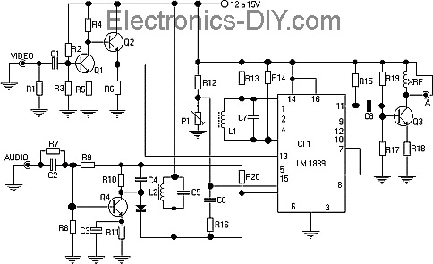
The coil L1 together with the capacitor in parallel, it generates the sign of 4,5 MHz that, modulated with the sound, it should be separate from the bearer of video of this frequency. Like this, the adjustment that should do in this coil it simply consists in you take it to 4,5 MHz, in way we obtain it sound.
The audio modulation ‚done by a varicap in a very simple way, so that the intensity of the audio sign obtained in most of the exits of the sound table it should provide a good reproduction.
The video sign, that obtained ‚of the video exit of any camera, videocassette, DVD, applied in the pin 13 of the circuit integrated after going by an amplification stage with two transistors.
This sign will modulate in width the video bearer whose frequency certain ‚for L2 and the capacitor in parallel.
We should adjust the frequency of this oscillator for the channel free from the strip of VHF, usually a channel baixo(2 to 6) in that the broadcasting station will operate.
The exit of RF, obtained in the pin 11 mischievous ‚to an amplifying stage with a transistor and of this for the antenna expresses or a telescopic antenna, in case the transmission is of short reach.
Observe that in the modulation of audio of this circuit, the sign generates two subportator being below a 4,5 MHz above the frequency of the channel and other 4,5 MHz.
As one of them not eliminated ‚, she can cause interferences in the adjacent channel. That means that you should choose a free channel in your place, but that doesn't have adjacent channels operating.
The feeding of the circuit can be made with tensions of 12 (7812)a 15(7815) Volts of a source with at least 1A and excellent filter. A deficient filter in this type of so much circuit can provoke snores in the sound, as undulations in the image.
Suggestion of power supply for circuit using the ic 7812
power supply for the tv transmitter using the integrate circuit 7812
Schematic for assembly of the tv transmitter with lm1889n
Circuit schematic for the tv transmitter with lm1889
Assembly of the circuit of the tv transmitter
The healthy resistors of 1/8W or larger. The power source so much can be the one of 12V/1A, as it can be made a modification to operate with 15V, being enough for that to change the transformer and the integrated circuit. The printed circuit board for the assembly ‚shown below in the illustration. The coils, as always, are the elements more critics of the project. L1 ‚formed by 40 you exhale of thread enameled fine (30 to 34) in a form of 5 diameter mm and 18 height mm, with nucleus of adjustable ferrite. The form for this coil can be obtained in old radios and televisions. The coil L2 that determines the frequency of the channel can have from 2 to 6 you exhale of thread 18 to 22, in used similar form her for L1. For 2 or 3 you exhale we will have the operation in the high channels of VHF, between the 7 and the 13, and for 4 to 6 you breathe the operation it will be among the channels 2 and 6. For the entrance of audio and video important ‚to use armored threads and appropriate connectors. For the antenna to use a connector for cable of 75 Ohms. The transmission section should not be in the same box that the source. The transmitter should be shielded for larger operation stability and to avoid the reception of noises that affect the transmission. The trimpot P1 has for purpose to adjust to component DC of the video sign, important to obtain the maximum revenue in the transmission.
Adjust alignment of the video, audio, the coils, antenna and frequency of the operation
Para to test and to adjust the transmitter, call in your entrance the exits of audio and video of a videocassette with any ribbon of good quality. Use appropriate cables. Tie the transmitter and, in that she intend to do the operation. The antenna of the transmitter can be a piece of some centimeters of covered common thread. Adjust the coil initially L1 so that the sign of maxim image intensity is captured. Adjustment the way trimpot to obtain the best image. Then, adjust slowly the coil L2 until obtaining the sound sign. Obtaining the sound sign, retouch the tuning of way L1 to obtain the maxim transmission. If it has difficulties in obtaining the tuning in the wanted channel, alter the value of C7 or I number it of you exhale of L1. If it has difficulties in tuning in the sound, alter C6 or then the number of you exhale of L2.
Printed circuit board for tv transmitter lm1889n
The board has dimensions of 11,2 x 7,0 cm .
Proven the operation, make the connection of the definitive antenna (it expresses or it interns) and re-do the way fittings to obtain the best transmission quality. After that, it is only to operate the station.
LIST OF MATERIAL
Source
CI1 - 7812 or 7815
D1 D4 1n4004 or equivalent
C1 C4 - 10NF
C5 - 2200µF TO 4700µF / 50 V
C6 - 100NF
C7 - 100µF 35V
C8 - 100NF
L1 - Shock of RF 100µH / 1 THE
T1 - Transformer, primary in agreement with the net (110/220) and secondary from 18 to 24V / 1A
Several - printed circuit board, threads, box, etc.
Transmitter
Semiconductors:
Cl1 - LM1889 - Integrated Circuit - Modulator of Video
Q1, Q2, Q4 - BC547 or equivalent
Q3 - BD135 or equivalent, example 2n2218 (different Pinage)
D1 - BB809 VARICAP or equivalent
Resistors 1/8W, 5%:
R1, R15 - 82 Ohms–
R2 - 120 K Ohms
R3 - 27K Ohms
R4 - 1,2 K Ohms
R5, R13, R14 - 270
R6 - 470 Ohms
R7 - 56k Ohms
R8 - 68k Ohms
R9 - 220 K Ohms
R10 - 2,7 K Ohms
R11, R17 - 1 K Ohms
R12, R16. R19 - 10 K Ohms
R18 - 47 Ohms x 1W
R20 - 22 K Ohms
P1 - 10 K Ohms trimpot
Capacitors:
C1 - 4,7µF/1 6V - ELECTROLYTIC
C2, C3 - 10µF/1 6V - ELECTROLYTIC
C4, C8 - 1 nF - ceramic
C5 - 120 pF - ceramic
C6 - 47 pF - ceramic
C7 - 56 pF or 47 pF - ceramic
Several:
L1, L2 - Coils - to see text--> Para who set up Lc meter L1 - 0.3µH and L2 - 7 to 13µH.
XRF - it Collides of 100 µH - to see text.
Several -printed board circuit , entrance Jacques and output of signal, box for assembly, power source, forms for the coils, enameled threads, etc.
Another TV Transmitter in that site.
Related Links
Downloads
TV Audio Video Transmitter - Link
|
|
|
| |
Accurate LC Meter
Build your own Accurate LC Meter (Capacitance Inductance Meter) and start making your own coils and inductors. This LC Meter allows to measure incredibly small inductances making it perfect tool for making all types of RF coils and inductors. LC Meter can measure inductances starting from 10nH - 1000nH, 1uH - 1000uH, 1mH - 100mH and capacitances from 0.1pF up to 900nF. The circuit includes an auto ranging as well as reset switch and produces very accurate and stable readings. |
|
PIC Volt Ampere Meter
Volt Ampere Meter measures voltage of 0-70V or 0-500V with 100mV resolution and current consumption 0-10A or more with 10mA resolution. The meter is a perfect addition to any power supply, battery chargers and other electronic projects where voltage and current must be monitored. The meter uses PIC16F876A microcontroller with 16x2 backlighted LCD. |
|
|
|
60MHz Frequency Meter / Counter
Frequency Meter / Counter measures frequency from 10Hz to 60MHz with 10Hz resolution. It is a very useful bench test equipment for testing and finding out the frequency of various devices with unknown frequency such as oscillators, radio receivers, transmitters, function generators, crystals, etc. |
|
1Hz - 2MHz XR2206 Function Generator
1Hz - 2MHz XR2206 Function Generator produces high quality sine, square and triangle waveforms of high-stability and accuracy. The output waveforms can be both amplitude and frequency modulated. Output of 1Hz - 2MHz XR2206 Function Generator can be connected directly to 60MHz Counter for setting precise frequency output. |
|
|
|
BA1404 HI-FI Stereo FM Transmitter
Be "On Air" with your own radio station! BA1404 HI-FI Stereo FM Transmitter broadcasts high quality stereo signal in 88MHz - 108MHz FM band. It can be connected to any type of stereo audio source such as iPod, Computer, Laptop, CD Player, Walkman, Television, Satellite Receiver, Tape Deck or other stereo system to transmit stereo sound with excellent clarity throughout your home, office, yard or camp ground. |
|
USB IO Board
USB IO Board is a tiny spectacular little development board / parallel port replacement featuring PIC18F2455/PIC18F2550 microcontroller. USB IO Board is compatible with Windows / Mac OSX / Linux computers. When attached to Windows IO board will show up as RS232 COM port. You can control 16 individual microcontroller I/O pins by sending simple serial commands. USB IO Board is self-powered by USB port and can provide up to 500mA for electronic projects. USB IO Board is breadboard compatible. |
|
|
|
|
ESR Meter / Capacitance / Inductance / Transistor Tester Kit
ESR Meter kit is an amazing multimeter that measures ESR values, capacitance (100pF - 20,000uF), inductance, resistance (0.1 Ohm - 20 MOhm), tests many different types of transistors such as NPN, PNP, FETs, MOSFETs, Thyristors, SCRs, Triacs and many types of diodes. It also analyzes transistor's characteristics such as voltage and gain. It is an irreplaceable tool for troubleshooting and repairing electronic equipment by determining performance and health of electrolytic capacitors. Unlike other ESR Meters that only measure ESR value this one measures capacitor's ESR value as well as its capacitance all at the same time. |
|
Audiophile Headphone Amplifier Kit
Audiophile headphone amplifier kit includes high quality audio grade components such as Burr Brown OPA2134 opamp, ALPS volume control potentiometer, Ti TLE2426 rail splitter, Ultra-Low ESR 220uF/25V Panasonic FM filtering capacitors, High quality WIMA input and decoupling capacitors and Vishay Dale resistors. 8-DIP machined IC socket allows to swap OPA2134 with many other dual opamp chips such as OPA2132, OPA2227, OPA2228, dual OPA132, OPA627, etc. Headphone amplifier is small enough to fit in Altoids tin box, and thanks to low power consumption may be supplied from a single 9V battery. |
|
|
|
|
|
Arduino Prototype Kit
Arduino Prototype is a spectacular development board fully compatible with Arduino Pro. It's breadboard compatible so it can be plugged into a breadboard for quick prototyping, and it has VCC & GND power pins available on both sides of PCB. It's small, power efficient, yet customizable through onboard 2 x 7 perfboard that can be used for connecting various sensors and connectors. Arduino Prototype uses all standard through-hole components for easy construction, two of which are hidden underneath IC socket. Board features 28-PIN DIP IC socket, user replaceable ATmega328 microcontroller flashed with Arduino bootloader, 16MHz crystal resonator and a reset switch. It has 14 digital input/output pins (0-13) of which 6 can be used as PWM outputs and 6 analog inputs (A0-A5). Arduino sketches are uploaded through any USB-Serial adapter connected to 6-PIN ICSP female header. Board is supplied by 2-5V voltage and may be powered by a battery such as Lithium Ion cell, two AA cells, external power supply or USB power adapter. |
|
200m 4-Channel 433MHz Wireless RF Remote Control
Having the ability to control various appliances inside or outside of your house wirelessly is a huge convenience, and can make your life much easier and fun. RF remote control provides long range of up to 200m / 650ft and can find many uses for controlling different devices, and it works even through the walls. You can control lights, fans, AC system, computer, printer, amplifier, robots, garage door, security systems, motor-driven curtains, motorized window blinds, door locks, sprinklers, motorized projection screens and anything else you can think of. |
|
|
|