| |
Class-A 12AU7 Tube Headphone Amplifier |
|
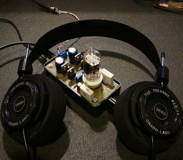
This is simple to build audiophile class-A tube headphone amplifier. It is based around 12AU7 / ECC82 audiophile vacuum tube that provides warm, rich and smooth sound expected from audiophile amplifiers. The 12AU7 (ECC82) is a Twin Triode vacuum tube, it is very popular in the audio world because it is rather rugged and can be operated at lower voltages. Headphone amplifier and 12AU7 tube is powered by just 12V DC voltage. This is great news for those new to vacuum tubes that want experience and learn more about them. Typically vacuum tubes operate at high and dangerous voltages so you must have some experience and know what you are doing. On the other hand this headphone amplifier operates at low 12V voltage so it is safe to build and experiment.
This simple headphone amplifier allows an entry level builder to experience assembling and listening to their own creation. I use the term builder as electronic experience combined with innovation which allows the creation of a device, rather than simple board stuffing. This amplifier can take on many shapes and sizes; I especially like when builders reuse older devices as cases and even recycle some components from various discarded power supplies. I try to keep price at a minimum because this amplifier is very basic and allows the builder to seek out theory, and actually "listen" to their music, and grow to build more complex projects in the future.
There are plenty of wonderful websites out there that can explain tube theory, I learned from the US Navy NEETS module 6. I will not go to in depth into the theory, but will introduce you to the 12AU7 (known in Europe as ECC82).
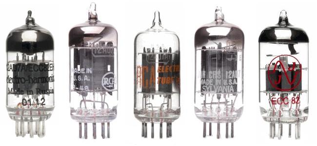
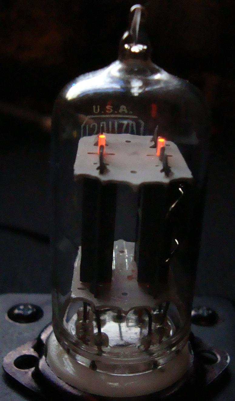
The 12AU7 (ECC82) is a Twin Triode vacuum tube, it is very popular in the audio world because it is rather rugged and can be operated at lower voltages. You will find these tubes in vintage amplifiers and organs. They are even used in older vacuum tube volt meters and their life span can reach into decades. The 12AU7 has an amplification factor (µ) of about 17, this is moderate as compared to its cousin the 12AX7 that comes in at 100. For purpose of the headphone amplifier the 12AU7 tube will be used in a common cathode configuration, and the incoming signal will be amplified by approximately 10dB. The 12AU7 is usually operated at plate voltages of over 120 volts, but fortunately it can be operated at lower voltages with decent results.
12AU7 (ECC82) Vacuum Tubes / Valves
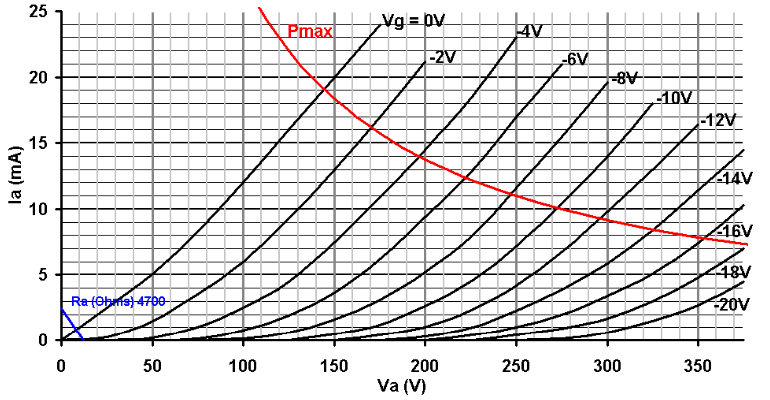
As you see in the load lone graph below, we will operate in the 6 volt region. 6 volts allows enough "swing" for the signal to reach 12 volts and down to the 0 volt line. Since this amplifier is single-ended we will not be applying an external negative voltage, but due to grid leak bias the voltage does sit above common.
12AU7 Load Line Graph
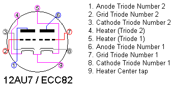
The tube has 9 pins and follows the EIA 9A pin out configuration. Remember that pin out diagrams are always read from the bottom of the tube, this little detail may save you much rework in the future.
12AU7 (ECC82) Tube Pinout Diagram
The great thing about this tube - it is basically two tubes in one. The other plus is that the heaters (filaments) can be powered by 6.3 or 12.6 volts AC or DC. In lower voltage amps, using DC for the heaters is preferred to reduce hum. For the this headphone amplifier we will be using a 12 volt sealed lead acid (SLA) battery as the power supply (hence v12). The two filaments are pinned 4 to 9 and 9 to 5, with pin 9 as a center tap. One can apply 12.6 volts across pins 4 and 5, or 6.3 volts to pins 4 and 5 with pin 9 used for common (negative), or 6.3 volts can be applied to pin 9 with pins 4 and 5 used as common.
Power Supply: 12AU7 (ECC82) / IRF510 Headphone Amp
The power supply is rather simple and straightforward, a 12v SLA battery. The battery is rated at 1.3 ampere-hour (Ah) and the total amplifier draw is about 400 mA, so we can expect some hours of playback between charges. A battery is the perfect source for voltage as there is no ripple or noise that will be injected into the signal, this is very important with headphone applications.
An alternate is a regulated switch mode power supply. I use a Cannon K30120 13v 1.8A portable printer power supply. The voltage is kept constant, great filtering, and most of all there is a built in over current protect. These power supplies can easily be found in thrift stores, the cost is miniscule to building a similar supply. It is important that the power supply be regulated to keep the unwanted noise levels low.
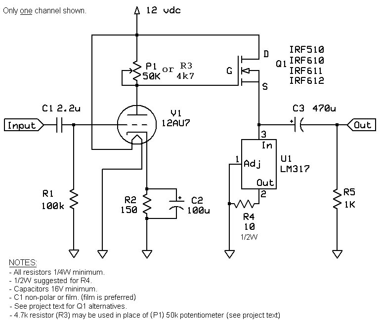
12AU7 (ECC82) / IRF510 Headphone Amp Circuit
The circuit consists of two stages: 1. a common cathode tube volt amp stage (gain), 2. a MOSFET source follower for current gain (with a LM317 regulator used as a constant current source). Since most headphones are less than 50 ohms a little current is necessary to run them efficiently.
12AU7 (ECC82) / IRF510 Headphone Amplifier Schematic
A Bipolar Junction Transistor (BJT) can be used in place of the MOSFET, but MOSFETs tend to be more stable with temperature and current shifts. Use caution when handling MOSFETs as they are very static sensitive.
The signal enters the grid via a coupling capacitor, it leaves the plate (anode) amplified and 180 degrees out of phase, it is then directly coupled to the gate of the MOSFET and leaves the source. The signal is then coupled to the headphones via a electrolytic capacitor, which blocks the DC from your headphones. Since the sleeve of your headphones is common it completes the circuit.
The MOSFET is biased into class-A operation and will be constantly conducting at approximately 125 mA. The LM317 regulator is configured as a constant current source and regulates at 125 mA in the given configuration. You can use the online LM317 regulator calculator to determine the current through the regulator by adjusting the program resistor. It is suggested that a 10 ohm 1/2W program resistors is used for R4 (you can use two 1/4W 20 ohm resistors in parallel). Note that the regulator and MOSFET devices will heat up and radiate heat. There are some real in depth calculations for heat, but know that the MOSFET can dissipate at least 1.6 Watts and the LM317 2 Watts to air, at room temp. I tested a prototype over a continuous 24 hours period in a 150 cubic-centimeter (about 9 cubic-inch) enclosure and there were no thermal stability issues. You can add heatsinks to the devices, just ensure that if you gang the FETs together to use mica and silicone washers to prevent the 12V supply from transferring to the heat sinks.
The schematic above shows only one channel, you will have to wire the the tube for both channels using different pins. The only wiring that is common for the 12AU7 tube between the two channels is the heater.
Construction Notes: 12AU7 (ECC82) / IRF510 Headphone Amp
With any project there are specialized tools that are required; in this project you will need some basic electronic test equipment and tools.
Ohm's Law deals with three basic measurements, Voltage, Resistance and Current. Knowing at least two of the variables, we can extrapolate a multitude of others. To make good readings, one must use a digital multimeter (DMM or DVOM). There are hundreds of DMMs on the market and you do not need to spend $200 on a DMM if you are only doing hobby work, but try to stay away from the very cheap $10 knock offs. One should use a meter that reads all three parameters and have probes that are safe up to 1000 volts.
The second most important tool is the soldering iron. You can use a soldering pencil, but for best results, a soldering station equivalent to the Weller WLC100 will save you headaches down the line. Nothing like leaving your soldering pencil on the table and finding it with your arm, or burning your laptop, etc.. Rosin core 60/40 solder is the best for new builders, there are others who swear by silver solder and other fancy solder, but for this application, the 60/40 flows well and will last years. Lastly purchase some liquid flux in a needle type applicator. Flux helps to transfer the heat to the joint, and will make the job so much easier. The solder has a flux core, but again the job will go much better with flux. Cleaning of the flux can be done with an acid brush and 99% isopropyl alcohol; you do not have to go crazy with cleaning, as the low voltage will not be an issue. Stay away from plumbing flux, it is conductive and can destroy your project.
Purchase some cheap headphones for testing. Similar to the ones you use on the airplane, nothing like frying your $300 Sennheiser headphones to make a project go upside down.
12AU7 (ECC82) / IRF510 Headphone Amp Parts
The bill of materials (BOM) is pretty straightforward, I selected readily available parts, 90% of them can be purchased at Radio Shack. If you have access to similar components, or you want to buy higher quality components, you can use Nichicon FG, KZ or Elna electrolytic capacitors and maybe Solen polypropylene film for C1. The only issue is shipping charges can make the project expensive, if you use a local Guitar Center and Radio Shack you can cut out shipping costs completely. The BOM for this 12AU7 (ECC82) / IRF510 Headphone Amp is provided
R1
R2
R3
R4
R5
U1
C1
C2
C3
Q1
Socket
V1
P1
Case
Mica
Heatsink
Jack
Battery
100k, 1/4W
150, 1/4W
4.7k, 1/4W
10, 1/4W
1k, 1/4W
LM317
2.2uF, 16V
100uF, 16V
470uF, 16V
IRF510
9pin PCB
12AU7
50k
12V 1.3Ah
N/A - Not Avalailable
* - 50-Piece 1/4-Watt Metal-Film Resistor Assortment, Radio Shack Part # 271-309
** - Misc Resistors at TubeDepot, it is suggested you use a 1/2W 10 ohm resistor for R4
*** - Misc 1/2W Resistors and Jacks available from Parts Express
R3 - A fixed resistor (R3) may be used in place of the 50k potentiometer (P1). 4k7 worked for many 12AU7 tube types, but you should pick a value to get half the supply voltage (see setting the bias Photograph 14).
Q1 - The MOSFET (Q1) can be replaced by an IRF610, IRF611 or IRF612, all of which will work as well. Stay away from IRF530 or IRF540 types (commonly found in power supplies) as there will be terrible roll-off of the highs.
C1 - Non-polarized electrolytic or film type capacitors may be used for C1 (2.2uF or greater). Most will find that a film type capacitor will sound best. Generic Polyester or Polypropylene types work well.
HEATSINKS - As previously noted, it is completely fine to run the MOSFETS and LM317 regulators to air, I did the math from the datasheets and the current is low enough to keep them stable. However, please do note that they do get hot. The metal tabs will sizzle water from your finger tip, like checking a clothes iron, but have not had a failure yet. There is not too much radiant heat though. If you are worried about heat you can use a small heat sink on the devices.
PCB: 12AU7 (ECC82) / IRF510 Headphone Amp
After a few years the circuit has been modified from my original 12AU7 Tube / IRF612 MOSFET Hybrid Headphone Amplifier build to fit on a single layer printed circuit board (PCB). Although it can easily be constructed point-to-point on a 750 hole proto board, a PCB is a cost effective upgrade. There are several sites that give in depth instructions on etching a PCB at home, and the whole process can be very rewarding. Just know that etching utilizes some very caustic and nasty chemicals, so proper ventilation and use of personal protective equipment (PPE) will make the process easy, fun and safe. Muriatic acid and hydrogen peroxide yielded the best results and also is much cheaper than ferric chloride.
The board layouts are included in the attachments; you can print them out and etch them using the toner transfer method.
I used the free version of the CADSOFT Eagle program to construct the board on a single plane. The process is done with a standard Toner Transfer method. Basically print the trace design onto cheap glossy photo paper. You must use a laser printer, or a Xerox copier on the darkest setting possible. The dark setting will allow the most toner to build up on the paper. Follow one of the many instruction set found online, I found the glossy magazine transfer method the best and easiest. You will have a transfer, just touch up and then finish the etching process. Another key note is to have a dremel press, or use two hands when drilling holes. Use the smallest bit possible then move up in size. If you remove too much copper, it will make the process of soldering cumbersome.
Copper Clad Board
After many modifications the PCB was reduced to a 2-1/4" x 4-3/4" and then down to 2" x 4" (50 x 100 mm) with thicker traces. The build is demonstrated on the first version (slightly larger PCB).
Assembly: 12AU7 (ECC82) / IRF510 Headphone Amp
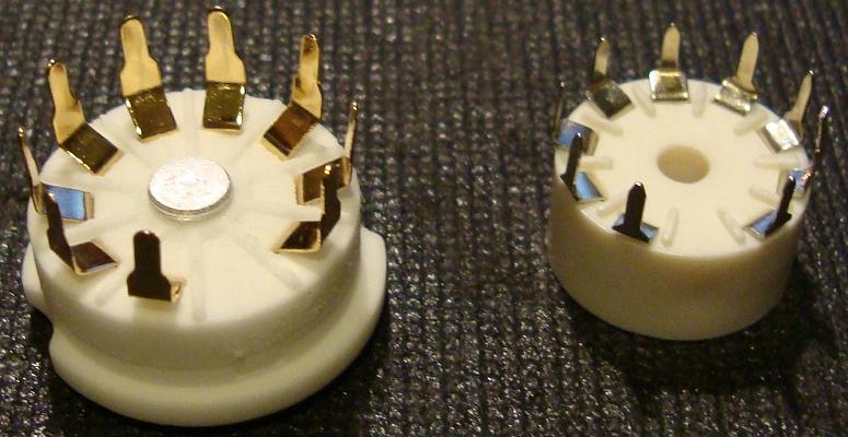
The components are fed through the top of the PCB and soldered onto the bottom (copper side). There are several types of 9 pin sockets, some will fit better than others, but with a little diligence either socket will work fine.
B9A 9-pin ceramic vacuum tube / valve socket
Photograph 3: B9A 9-pin ceramic vacuum tube / valve socket
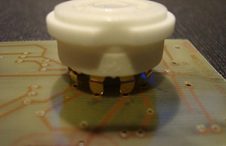
Solder in the tube socket, the pins will fit in the hole pattern, just use caution not to overstress the pins or they will break.
9-pin vacuum tube / valve socket on PCB
Photograph 4: 9-pin vacuum tube / valve socket on PCB
Solder the resistors next, the PCB spacing is for 1/4 watt metal film types, if you only have 1/2 watt or higher resistors, you will have to bend the leads to fit the PCB.
Bend Resistor Leads to Fit on PCB
Photograph 5: Bend Resistor Leads to Fit on PCB
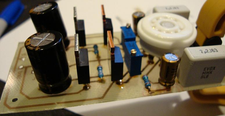
After populating resistors, solder in the capacitors. The C1 capacitors are polyester film types (non-polar) and can be placed in either direction. The remaining capacitors are electrolytic, and must follow proper polarity. C2 has the ground pin facing the tube, and C3 have the ground pin facing back.
Populate 12AU7 / IRF510 Tube Headphone Amp
Photograph 6: Populating the PCB
Solder the MOSFETS, LM317voltage regulators, and the remaining components.
Populate 12AU7 Tube / IRF510 Mosfet Headphone Amp
Photograph 7: Populating the PCB
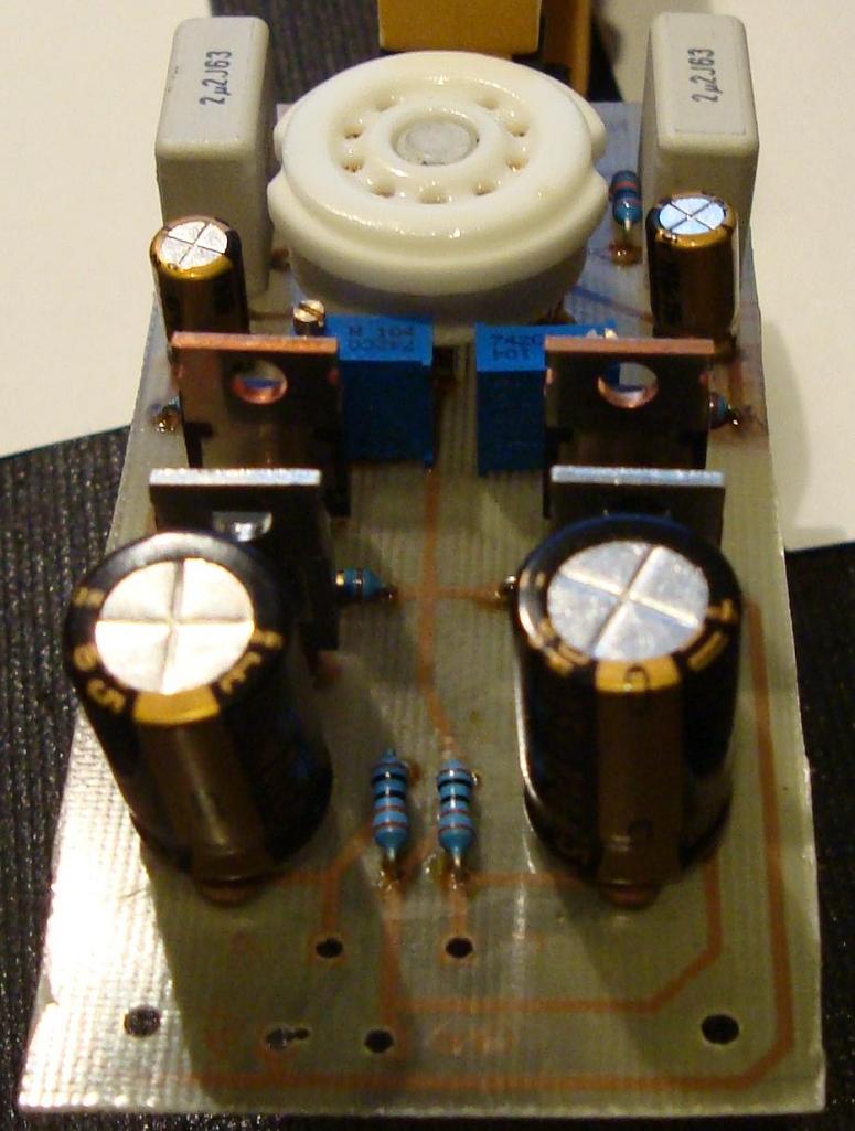
Solder in the power jack, which in this case is a terminal block. If you prefer, you can run wires to a jack on the enclosure.
Populate 12AU7 Valve / IRF510 Mosfet Headphone Amp
Photograph 8: Populating the PCB
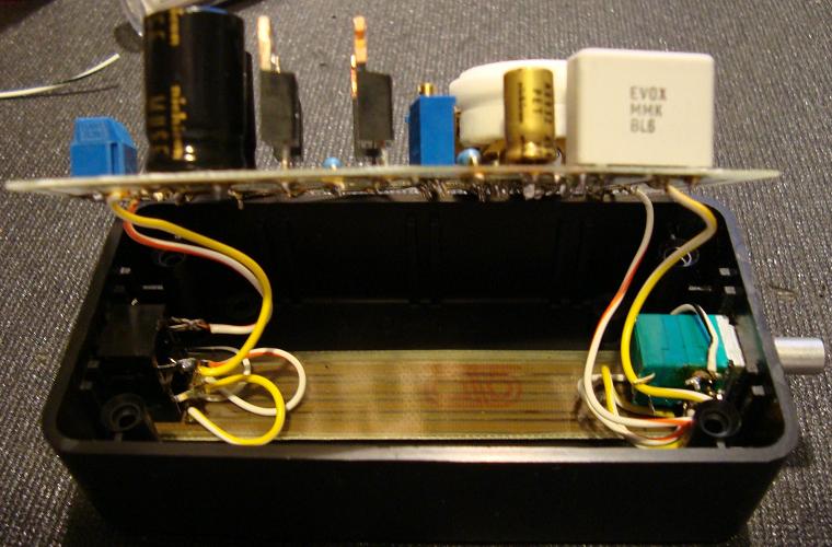
Test fit the PCB into the enclosure and trim the sides as necessary.
Dry fit the PCB into the enclosure
Photograph 9: Dry fit the PCB into the enclosure
With the board complete, prepare the case for the sockets and volume potentiometer. A stepped drill bit works great for drilling the holes into the enclosure.
Chassis for 12AU7 Tube / IRF510 Mosfet Headphone Amp
Photograph 10: Chassis Preparation for 12AU7 Tube / IRF510 Mosfet Headphone Amp
The input signal is fed into the right side of the enclosure via a set of RCA jack or can use a 3.5 mm stereo jack if you prefer. The signal comes in through the jack and to the potentiometer which allows level control and then to the circuit for amplification. The output exits the amplifier via the output jack. If your signal source allows you to control the signal level, you can omit the potentiometer. The Radio Shack potentiometer can be used, but the fit will be tight so to prevent a short, you may want to use a smaller Alps 10k audio pot (part number RK0971221Z05)
Alps Potentiometer for 12AU7 / IRF510 Headphone Amp
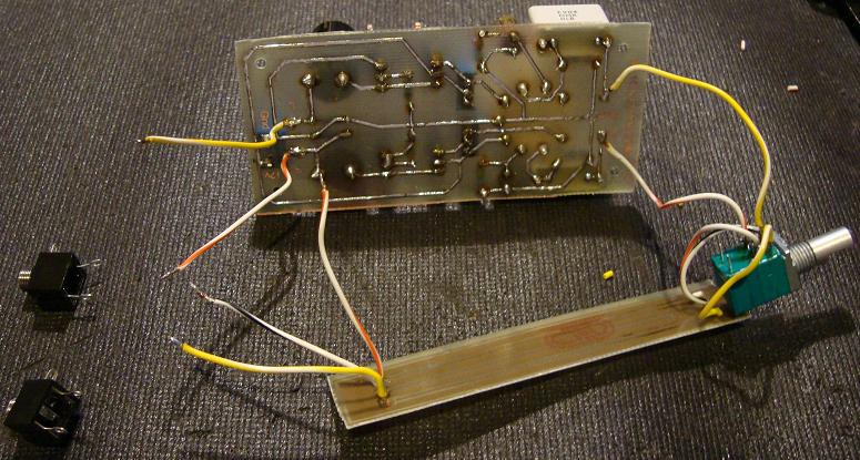
I have drafted a routing PCB (see the previous PCB section), but three small gauge wires will work fine too. Solder all connections before mounting. Mount the jacks and potentiometer and leave the amp board free for testing.
Putting 12AU7 / IRF510 Headphone Amp Together
The positive lead from C3 is the same potential as the MOSFET source pin. It is best to check voltage at the capacitor, because the MOSFET can be damaged if the pins are shorted. Also, check that both heaters glow.
Check that 12AU7 Tube Heaters are Working
Photograph 13: Check that 12AU7 Tube Heaters are Working
Setting the Bias
The bias is set by adjusting the 50k trim potemtiometer (P1) until the output side of the MOSFET (Source) is at one-half of the supply voltage (Drain). Adjusting the two trim potemtiometers to one-half of your supply voltage, 6 volts since we are using a 12v supply. You will want to check and reset the bias a few times in the first few hours of use as it will drift while everything settles in.
Setting the Bias
Check for DC Offset
Next check for DC offset at the headphone output using a DMM. The DC offset should be less than 10 mV. After a number of prototypes I measured 8 mV max and typically about 3 mV.
Check for DC Offset at the Output
Photograph 15: Check for DC Offset at the Output
Now its time to hook up the cheap headphones for a quick listen.
Check Headphone Amplifier with Cheap Headphones
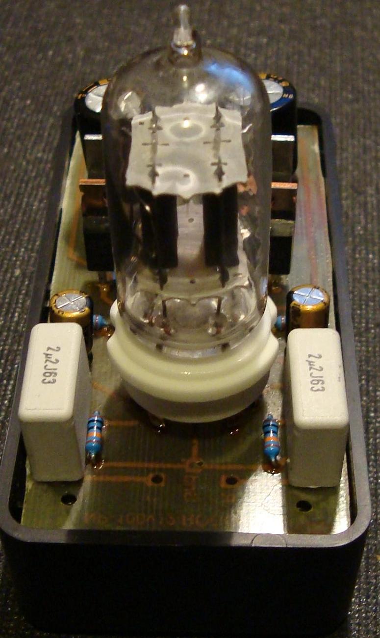
If all is good, secure the amp to the case, one more check with the cheap headphones, then try out your new amp.
Finished 12AU7 Tube / IRF510 Mosfet Headphone Amplifier
Now its time to listen to audiophile tube sound. Enjoy!
Related Links
Downloads
Class-A 12AU7 Tube Headphone Amplifier - Link
|
|
|
| |
Accurate LC Meter
Build your own Accurate LC Meter (Capacitance Inductance Meter) and start making your own coils and inductors. This LC Meter allows to measure incredibly small inductances making it perfect tool for making all types of RF coils and inductors. LC Meter can measure inductances starting from 10nH - 1000nH, 1uH - 1000uH, 1mH - 100mH and capacitances from 0.1pF up to 900nF. The circuit includes an auto ranging as well as reset switch and produces very accurate and stable readings. |
|
PIC Volt Ampere Meter
Volt Ampere Meter measures voltage of 0-70V or 0-500V with 100mV resolution and current consumption 0-10A or more with 10mA resolution. The meter is a perfect addition to any power supply, battery chargers and other electronic projects where voltage and current must be monitored. The meter uses PIC16F876A microcontroller with 16x2 backlighted LCD. |
|
|
|
60MHz Frequency Meter / Counter
Frequency Meter / Counter measures frequency from 10Hz to 60MHz with 10Hz resolution. It is a very useful bench test equipment for testing and finding out the frequency of various devices with unknown frequency such as oscillators, radio receivers, transmitters, function generators, crystals, etc. |
|
1Hz - 2MHz XR2206 Function Generator
1Hz - 2MHz XR2206 Function Generator produces high quality sine, square and triangle waveforms of high-stability and accuracy. The output waveforms can be both amplitude and frequency modulated. Output of 1Hz - 2MHz XR2206 Function Generator can be connected directly to 60MHz Counter for setting precise frequency output. |
|
|
|
BA1404 HI-FI Stereo FM Transmitter
Be "On Air" with your own radio station! BA1404 HI-FI Stereo FM Transmitter broadcasts high quality stereo signal in 88MHz - 108MHz FM band. It can be connected to any type of stereo audio source such as iPod, Computer, Laptop, CD Player, Walkman, Television, Satellite Receiver, Tape Deck or other stereo system to transmit stereo sound with excellent clarity throughout your home, office, yard or camp ground. |
|
USB IO Board
USB IO Board is a tiny spectacular little development board / parallel port replacement featuring PIC18F2455/PIC18F2550 microcontroller. USB IO Board is compatible with Windows / Mac OSX / Linux computers. When attached to Windows IO board will show up as RS232 COM port. You can control 16 individual microcontroller I/O pins by sending simple serial commands. USB IO Board is self-powered by USB port and can provide up to 500mA for electronic projects. USB IO Board is breadboard compatible. |
|
|
|
|
ESR Meter / Capacitance / Inductance / Transistor Tester Kit
ESR Meter kit is an amazing multimeter that measures ESR values, capacitance (100pF - 20,000uF), inductance, resistance (0.1 Ohm - 20 MOhm), tests many different types of transistors such as NPN, PNP, FETs, MOSFETs, Thyristors, SCRs, Triacs and many types of diodes. It also analyzes transistor's characteristics such as voltage and gain. It is an irreplaceable tool for troubleshooting and repairing electronic equipment by determining performance and health of electrolytic capacitors. Unlike other ESR Meters that only measure ESR value this one measures capacitor's ESR value as well as its capacitance all at the same time. |
|
Audiophile Headphone Amplifier Kit
Audiophile headphone amplifier kit includes high quality audio grade components such as Burr Brown OPA2134 opamp, ALPS volume control potentiometer, Ti TLE2426 rail splitter, Ultra-Low ESR 220uF/25V Panasonic FM filtering capacitors, High quality WIMA input and decoupling capacitors and Vishay Dale resistors. 8-DIP machined IC socket allows to swap OPA2134 with many other dual opamp chips such as OPA2132, OPA2227, OPA2228, dual OPA132, OPA627, etc. Headphone amplifier is small enough to fit in Altoids tin box, and thanks to low power consumption may be supplied from a single 9V battery. |
|
|
|
|
|
Arduino Prototype Kit
Arduino Prototype is a spectacular development board fully compatible with Arduino Pro. It's breadboard compatible so it can be plugged into a breadboard for quick prototyping, and it has VCC & GND power pins available on both sides of PCB. It's small, power efficient, yet customizable through onboard 2 x 7 perfboard that can be used for connecting various sensors and connectors. Arduino Prototype uses all standard through-hole components for easy construction, two of which are hidden underneath IC socket. Board features 28-PIN DIP IC socket, user replaceable ATmega328 microcontroller flashed with Arduino bootloader, 16MHz crystal resonator and a reset switch. It has 14 digital input/output pins (0-13) of which 6 can be used as PWM outputs and 6 analog inputs (A0-A5). Arduino sketches are uploaded through any USB-Serial adapter connected to 6-PIN ICSP female header. Board is supplied by 2-5V voltage and may be powered by a battery such as Lithium Ion cell, two AA cells, external power supply or USB power adapter. |
|
200m 4-Channel 433MHz Wireless RF Remote Control
Having the ability to control various appliances inside or outside of your house wirelessly is a huge convenience, and can make your life much easier and fun. RF remote control provides long range of up to 200m / 650ft and can find many uses for controlling different devices, and it works even through the walls. You can control lights, fans, AC system, computer, printer, amplifier, robots, garage door, security systems, motor-driven curtains, motorized window blinds, door locks, sprinklers, motorized projection screens and anything else you can think of. |
|
|
|