| |
Class-A Mosfet Headphone Amplifier |
|
Not thrilled with how a computer soundcard drove my 32ohm headphones so I decided to build myself class-A mosfet headphone amplifier. As with most of my projects, the goal was to keep it simple, keep cost down and try use some salvaged parts. This is a simple do-it-yourself (DIY) headphone amplifier project that is fashioned primarily after the Class A MOSFET Headphone Driver project by Greg Szekeres and to some extent Mark's DIY Class A 2SK1058 MOSFET Amplifier Project. The amplifier concept is simple and follows a typical single-ended class A circuit utilizing an active constant current source (CCS) in place of a passive resistor. A CCS doubles the efficiency of the circuit over that where a passive load resistor is used, bringing it to a maximum of 25%.

There are a couple of items to note. A FET follower circuit will be able to supply high current, but the voltage gain will be less than one. This amplifier will only be suitable in applications where the input signal does not require voltage amplification (such as the output of an mp3 player or computer). Also, a simple single-ended circuit like this will have no power supply ripple rejection and thus any noise in the power supply is going to go right through amplifier. For that reason, you will need to use a regulated power supply. Suitable inexpensive regulated (wall wart) power supplies can be purchased from Radio Shack. 10-20VDC and 750mA should be fine.
The schematic for this project is shown below in Figure 2. An IRF610 MOSFET is used in this example, but a wide variety of FET devices can be used in its place. A LM317 voltage regulator is used for the CCS and the draw is set at 250mA.
DIY Headphone Amplifier Construction
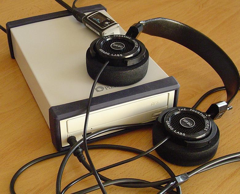
This headphone amplifier will reside primarily on my desk at work, so it needs to fit into an office environment. Fortunately I had a dead Plextor external CD-ROM kicking around that would make for the perfect enclosure and blend in well on my desk. Even better yet, it already had a power switch, power adapter receptacle and RCA inputs on the back as well as a headphone jack on the front. Perfect! The open hole you see on the back is where the USB header resided, but I had previously salvaged that for another project.
Plextor External CD-ROM Enclosure
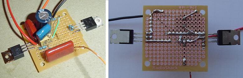
The amplifier is constructed on ~1.75" square protoboards from Radio Shack (276-148), but any board will work. I only used parts that I had on hand and you can see that I did not use any boutique parts. Plain (but matched) metal film resistors, 1uF mylar input cap and 0.47uF polypropylene bypass cap on the output. The 0.1uF decoupling capacitor is also polypropylene. Some may prefer to use higher quality input and bypass caps and that should improve the sound. You can use carbon resistors, but I suggest you use metal film, particularly for the CCS due to their superior temperature stability over carbon.
DIY Headphone Amplifier on Protoboard
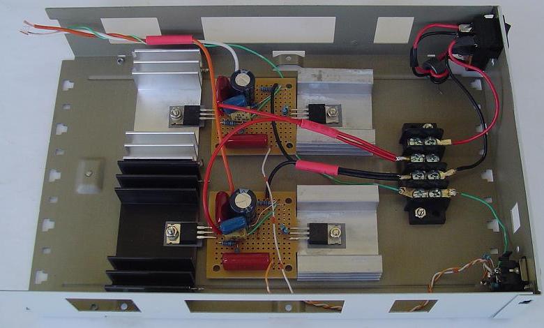
The heat sinks were salvaged from various dead components. The smaller heat sinks are about 1.75" square and only get moderately warm, but keep in mind that the heat sinks are attached to the metal chassis which also helps dissipate some heat. Be sure to isolate the MOSFET and regulator from the heat sinks.
Construction of Headphone Amplifier
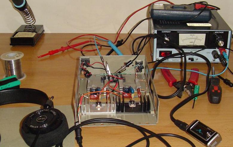
The headphone amplifier was first tested (smoke test) using a regulated power supply at very low voltage. The bias is set by varying the 100k variable resistor until the output side of the MOSFET (Source) is at one-half of the supply voltage (Drain). You will want to check and reset the bias a few times in the first few hours as it will drift while everything settles in. The amp worked well between 10 and 20VDC, but seemed to work best at 13V and up. With a regulated supply there was no audible hum. That was not the case with an unregulated supply.
Setting Headphone Amplifier Bias
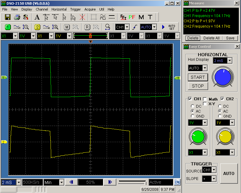
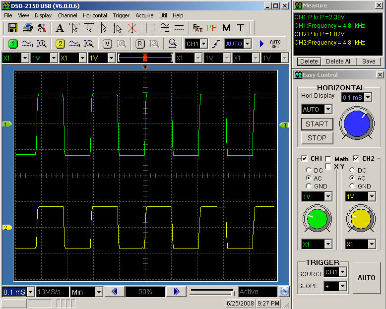
Next I got a chance to try out my new USB oscilloscope. It is a DSO-2150 which is a dual trace scope with 60MHz bandwidth and a maximum sample rate of 150MS/s. For those interested in such oscilloscopes here is a little more information about my experience with the DSO-2150 USB PC Based Oscilloscope. I checked the sine wave response and as expected, the results were good across 20Hz to 20kHz (the limits of my function generator). Below are two screen shots of the square wave response at 100Hz and 4800Hz.
The top trace (green) is the input waveform and the bottom trace (yellow) is the output. My signal generator is not great and that is reflected in the quality of the input waves. If you compare the input voltage to the output voltage you will see than the gain of the circuit is about 0.8. As you can see in the 100Hz trace, the square wave response is slightly tilted but stable. Tilting gradually decreases as the frequency increases and beyond about 300Hz the square wave response is excellent up to 20kHz which is the limit of my signal generator. Since music is comprised primarily of sine waves this is not a problem as the sine wave response was fine across the audible range.
The final touches were to epoxy the CD-ROM faceplate to an aluminum plate and put the enclosure back together. Since an mp3 player or computer will be used to control the volume, there is no potentiometer on the amplifier. The original volume control knob from the CD-ROM was cut down and glued in place.
Finished Class-A Mosfet Headphone Amplifier
For a simple single-ended amplifier design, the sound is pretty good to my ears. The amp drives my Grado SR80 headphones with ease, while my portable mp3 does not. I even prefer the sound compared to the built-in integrated headphone amp on my NAD C162 preamp.

Related Links
Downloads
Class-A Mosfet Headphone Amplifier - Link
|
|
|
| |
Accurate LC Meter
Build your own Accurate LC Meter (Capacitance Inductance Meter) and start making your own coils and inductors. This LC Meter allows to measure incredibly small inductances making it perfect tool for making all types of RF coils and inductors. LC Meter can measure inductances starting from 10nH - 1000nH, 1uH - 1000uH, 1mH - 100mH and capacitances from 0.1pF up to 900nF. The circuit includes an auto ranging as well as reset switch and produces very accurate and stable readings. |
|
PIC Volt Ampere Meter
Volt Ampere Meter measures voltage of 0-70V or 0-500V with 100mV resolution and current consumption 0-10A or more with 10mA resolution. The meter is a perfect addition to any power supply, battery chargers and other electronic projects where voltage and current must be monitored. The meter uses PIC16F876A microcontroller with 16x2 backlighted LCD. |
|
|
|
60MHz Frequency Meter / Counter
Frequency Meter / Counter measures frequency from 10Hz to 60MHz with 10Hz resolution. It is a very useful bench test equipment for testing and finding out the frequency of various devices with unknown frequency such as oscillators, radio receivers, transmitters, function generators, crystals, etc. |
|
1Hz - 2MHz XR2206 Function Generator
1Hz - 2MHz XR2206 Function Generator produces high quality sine, square and triangle waveforms of high-stability and accuracy. The output waveforms can be both amplitude and frequency modulated. Output of 1Hz - 2MHz XR2206 Function Generator can be connected directly to 60MHz Counter for setting precise frequency output. |
|
|
|
BA1404 HI-FI Stereo FM Transmitter
Be "On Air" with your own radio station! BA1404 HI-FI Stereo FM Transmitter broadcasts high quality stereo signal in 88MHz - 108MHz FM band. It can be connected to any type of stereo audio source such as iPod, Computer, Laptop, CD Player, Walkman, Television, Satellite Receiver, Tape Deck or other stereo system to transmit stereo sound with excellent clarity throughout your home, office, yard or camp ground. |
|
USB IO Board
USB IO Board is a tiny spectacular little development board / parallel port replacement featuring PIC18F2455/PIC18F2550 microcontroller. USB IO Board is compatible with Windows / Mac OSX / Linux computers. When attached to Windows IO board will show up as RS232 COM port. You can control 16 individual microcontroller I/O pins by sending simple serial commands. USB IO Board is self-powered by USB port and can provide up to 500mA for electronic projects. USB IO Board is breadboard compatible. |
|
|
|
|
ESR Meter / Capacitance / Inductance / Transistor Tester Kit
ESR Meter kit is an amazing multimeter that measures ESR values, capacitance (100pF - 20,000uF), inductance, resistance (0.1 Ohm - 20 MOhm), tests many different types of transistors such as NPN, PNP, FETs, MOSFETs, Thyristors, SCRs, Triacs and many types of diodes. It also analyzes transistor's characteristics such as voltage and gain. It is an irreplaceable tool for troubleshooting and repairing electronic equipment by determining performance and health of electrolytic capacitors. Unlike other ESR Meters that only measure ESR value this one measures capacitor's ESR value as well as its capacitance all at the same time. |
|
Audiophile Headphone Amplifier Kit
Audiophile headphone amplifier kit includes high quality audio grade components such as Burr Brown OPA2134 opamp, ALPS volume control potentiometer, Ti TLE2426 rail splitter, Ultra-Low ESR 220uF/25V Panasonic FM filtering capacitors, High quality WIMA input and decoupling capacitors and Vishay Dale resistors. 8-DIP machined IC socket allows to swap OPA2134 with many other dual opamp chips such as OPA2132, OPA2227, OPA2228, dual OPA132, OPA627, etc. Headphone amplifier is small enough to fit in Altoids tin box, and thanks to low power consumption may be supplied from a single 9V battery. |
|
|
|
|
|
Arduino Prototype Kit
Arduino Prototype is a spectacular development board fully compatible with Arduino Pro. It's breadboard compatible so it can be plugged into a breadboard for quick prototyping, and it has VCC & GND power pins available on both sides of PCB. It's small, power efficient, yet customizable through onboard 2 x 7 perfboard that can be used for connecting various sensors and connectors. Arduino Prototype uses all standard through-hole components for easy construction, two of which are hidden underneath IC socket. Board features 28-PIN DIP IC socket, user replaceable ATmega328 microcontroller flashed with Arduino bootloader, 16MHz crystal resonator and a reset switch. It has 14 digital input/output pins (0-13) of which 6 can be used as PWM outputs and 6 analog inputs (A0-A5). Arduino sketches are uploaded through any USB-Serial adapter connected to 6-PIN ICSP female header. Board is supplied by 2-5V voltage and may be powered by a battery such as Lithium Ion cell, two AA cells, external power supply or USB power adapter. |
|
200m 4-Channel 433MHz Wireless RF Remote Control
Having the ability to control various appliances inside or outside of your house wirelessly is a huge convenience, and can make your life much easier and fun. RF remote control provides long range of up to 200m / 650ft and can find many uses for controlling different devices, and it works even through the walls. You can control lights, fans, AC system, computer, printer, amplifier, robots, garage door, security systems, motor-driven curtains, motorized window blinds, door locks, sprinklers, motorized projection screens and anything else you can think of. |
|
|
|