| |
Together with a good directional antenna this high performance two-stage antenna amplifier for the VHF FM broadcast band will enable you to receive distant radio stations. VHF FM Antenna booster will also drastically improve reception of FM signals you’ve come to accept as marginal and noisy in your area. Antenna booster is also great for extending transmission range of low power VHF / FM transmitters.
For various reasons, an increasing number of people are not satisfied with the quality of radio signals that can be received via cable systems. Unfortunately, cross-modulation, and other nasty effects created in the head end station are in stark contrast with the superb quality of high-end FM tuners that can be bought commercially.
Not surprisingly, owners of such tuners will often prefer to have their own antenna on the roof. Add to that a high-performance FM antena booster like the one described here and you can start DXing as well as enjoying high-quality stereo reception. The author employs the present amplifier in combination with a Sangean ATS-803 World band receiver, a Philips RR-571 tuner and a single-element cubical quad directional antenna at a height of just 15 feet. Using this setup he is able to receive FM stations as far off as 500 km.
Antenna booster circuit description
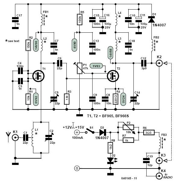
In the design we’re about to describe you’ll find the following important parameters coupled: low noise figure (approx. 1 dB); high gain (up to 40 dB) and low susceptibility to intermodulation products. Yet the amplifier is inexpensive and easy to build. The circuit diagram in Figure 1 reveals the secret: dual-gate MOSFETs in positions T1 and T2. The first of these, T1, is configured mainly for low noise and antenna matching and the second, T2, for high gain. Unusually, the antenna signal is applied to T1 via its source (S) terminal, which is convenient because unlike one of the gates (G1 and G2) it already represents a fairly low impedance. None the less, for impedance matching with the 50 Ω coax cable a tap needs to be used on tuned filter L1/C2.
For VHF and UHF amplifiers, DG-MOSFETs represent a good alternative to cheap but noisy bipolar transistors and very expensive and difficult to get Ga-As FETs.
The gain of the second DG-MOSFET in the circuit is adjustable using preset P1 which varies the bias voltage to T2’s G2 terminal — this is the classic way of controlling the gain of a DGMOSFET and it still works very well. Such a control is included in the design to allow you to get the exact amount of gain required for your particular application. For example, if you live near a powerful VHF FM or TV broadcast transmitter then you’ll find that a lot of gain produces cross-modulation and other unwanted effects like coupled oscillation and ‘birdies’ within the FM band.
For stability the supply voltage is decoupled at several locations by electrolytic capacitors and ceramic capacitors for the low and high frequencies respectively. To enable it to be mounted as close as possible to the antenna, the amplifier is powered via the download coax cable, i.e., over coax connectors connected to K2 and K3. In the supply, the RF signal is taken off the coax core by capacitor C19.
The supply voltage is adjustable to some extent with pot P2, which will also allow a degree of gain control. The current through ‘power on’ LED D2 should be about 10 mA. If a low-current LED is used, then R8 has to be increased accordingly. With electrical safety in mind we strongly suggest the use of a mains adapter with 12 VDC output. Depending on the gain set and the DG-MOSFETs used the circuit will consume about 50 mA so a 100-mA or slightly more powerful adapter will be fine in most cases.
VHF FM antenna amplifier construction
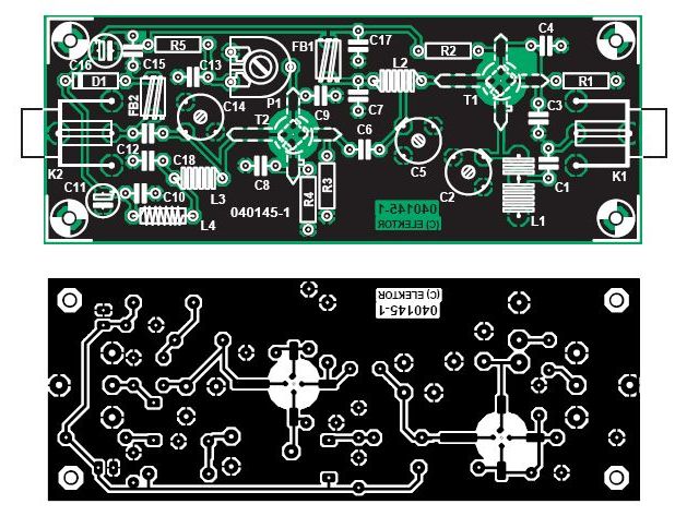
The amplifier is built on the singlesided printed circuit board shown in Figure 2. The inductors in the design are all very simple to make, see the parts list for construction details. L1, L2 and L3, are wound on a 4.5-mm dia. drill or pencil. L1 then needs to be stretched to a length of about 10 mm. You’ll find that a relatively large resistor is needed to wind choke L4 on — we used a 0.5-watt carbon-film resistor from the junkbox (metal film resistors seem to have taken over completely). The value 1 MΩ is uncritical, what we’re after is ‘a lot’ of carbon for the core so 820 k or 1.2 M will do just as well.
FM antenna booster PCB layout
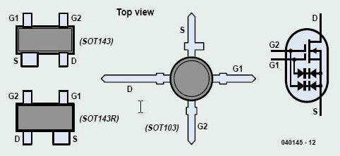
The DG-MOSFETs are not only sensitive to static discharges but also easy to fit the wrong way around. The non-SMD versions require 5-mm holes t be drilled in the PCB. Make absolutely sure you know each MOSFET’s final orientation on the board before soldering it in place — check, think hard and refer to the component drawing shown in Figure 1. You may find that the legs are a bit too long for the PCB but don’t use your cutters until the very last moment because without the stud marker (source terminal) you will be lost for device orientation.
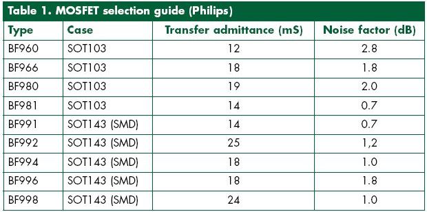
Several VHF/UHF DG-MOSFETs may be used in this circuit — see Table 1. With some dexterity it is also possible to use SMD devices. In general, you should aim to use a BF9xx with a low noise figure, although that may imply a slightly reduced overall gain. Remember, however, that the amplifier’s gain is secondary to the noise figure — in practice, any gain between 25 dB and 40 dB will be just fine.
The power supply parts are not accommodated on a PCB but may be connected up using flying lead construction in a small case. The finished PC should be cleaned with isopropyl alcohol to remove solder residu.
The amplifier must be housed in a metal case with proper coax connectors used for K1 and K2. The author used F-type sockets as customary with satellite TV rigs. They are cheap and easy to obtain. However, BNC sockets may be used equally well. The connections between the sockets and the amplifier input and output should be kept as short as possible using thin coax cable like RG174/U.
VHF Antenna Setting up
Give the PCB a final, thorough inspection for bad soldering, wrong components, etc., and resolve all problems before proceeding.
Set all presets and trimmers to the centre of their travel. Apply power to the amplifier and check the various test voltages indicated in the circuit diagram. These voltages are typical and should not be taken to mean the ‘law’. Tune your VHF FM radio to a weak signal at around 98 MHz. Tune the amplifier back to front, that is, first C14, then C5 and then C2 for best reception — your ears and the tuner’s S meter will tell you what’s happening. If necessary reduce or increase the gain using P1. A good way to simulate a weak signal is to turn the antenna away from the transmitter direction.
The amplifier’s 3-dB bandwidth will be about 10 MHz with all tuned elements at the centre frequency. By careful retuning of the three trimmer capacitors (‘staggering’), this may be widened to 20-25 MHz at the cost of some gain. Fine tuning may also be achieved by stretching or compressing the three air-spaced inductors. This method may be for specialists only, however.
Other bands
The amplifier may be modified for use at slightly higher frequencies like 120 MHz (VHF airband), 145 MHz (2-m radio amateur band or even 146- 174 MHz (PMR band). Some experience may be required in tweaking the inductors for resonance at their new frequency however. If you find that a particular trimmer no longer ‘peaks’ then the L/C combination is out of range. Lacking specialised test equipment like a grid dipper to see where it does resonate, go for trial and error by fitting an inductor with fewer turns and see what happens then. Whatever the frequency, the booster will not fail to give the kiss of life to a duff receiver.
COMPONENTS LIST
Resistors:
R1 = 10kΩ
R2 = 150kΩ
R3 = 1MΩ
R4 = 220Ω
R5 = 100kΩ
R6 = 3Ω3
R7 = 1kΩ
R8 = 1kΩ2*
P1 = 47kΩ preset H
P2 = 10kΩ linear potentiometer
Capacitors:
C1, C6 = 22pF ceramic
C2, C5, C14 = 22pF trimmer
C3, C7, C17, C18 = 1nF ceramic
C4, C9, C13, C15 = 100nF ceramic
C8, C10 = 10nF ceramic
C11, C16 = 100μF 25V radial
C12 = 3pF9 ceramic
C19 = 12pF ceramic
Semiconductors:
D1,D3 = 1N4007
D2 = LED
T1,T2 = BF965 or BF966S
Inductors:
FB1,FB2,FB3 = 5 turns 0.15 mm (38SWG) enamelled copper wire on ferrite bead
L1 = 7 turns 0.9 mm dia. (20SWG) enamelled copper wire; internal dia. 5mm; length 10mm; tap at 5 turns from ground
L2,L3 = 7 turns 0.9 mm dia. (20SWG), internal dia. 5mm; closewound
L4 = 30 turns 0.15mm dia (38SWG) enamelled copper wire on a 1MΩ 0.5W resistor
Miscellaneous:
K1-K4 = F socket, PCB mount
S1 = on/off switch, 1 contact
All change to SMD
Although the BF966 DG-MOSFET is no longer produced, it is still around in electronics retail and surplus circuits. Broadly speaking, DG-MOSFETs from the BF9xx series in the ‘traditional‘ SOT103 case are being superseded fast by their SMD (SOT143) counterparts.
These are perfect electrical replacements but require short wires in order to be fitted on a board laid of for a SOT103 transistor. In many cases, the type number is that of the SOT103 parent device plus an offset. For example, a BF966S is electrically compatible with the BF996S, and the same applies to the BF981 and its successor the BF991.
A further interesting point to note is that the –R suffix in the type code of SOT143 DG-MOSFETs indicates a ‘reflected’ pinout. The layout of the PCB designed for the antenna booster allows both SMD (SOT143) and ‘leaded’ (SOT103) DG-MOSFETs from the BF9xx series to be fitted, the latter being mounted recessed in a 5-mm hole allowing their terminals to be soldered flush with the PCB tracks. Unfortunately, ‘-R’ suffix SOT143 DG-MOSFETs cannot be used on this board.
Related Links
Downloads
VHF FM Antenna Booster - Link
|
|
|
| |
Accurate LC Meter
Build your own Accurate LC Meter (Capacitance Inductance Meter) and start making your own coils and inductors. This LC Meter allows to measure incredibly small inductances making it perfect tool for making all types of RF coils and inductors. LC Meter can measure inductances starting from 10nH - 1000nH, 1uH - 1000uH, 1mH - 100mH and capacitances from 0.1pF up to 900nF. The circuit includes an auto ranging as well as reset switch and produces very accurate and stable readings. |
|
PIC Volt Ampere Meter
Volt Ampere Meter measures voltage of 0-70V or 0-500V with 100mV resolution and current consumption 0-10A or more with 10mA resolution. The meter is a perfect addition to any power supply, battery chargers and other electronic projects where voltage and current must be monitored. The meter uses PIC16F876A microcontroller with 16x2 backlighted LCD. |
|
|
|
60MHz Frequency Meter / Counter
Frequency Meter / Counter measures frequency from 10Hz to 60MHz with 10Hz resolution. It is a very useful bench test equipment for testing and finding out the frequency of various devices with unknown frequency such as oscillators, radio receivers, transmitters, function generators, crystals, etc. |
|
1Hz - 2MHz XR2206 Function Generator
1Hz - 2MHz XR2206 Function Generator produces high quality sine, square and triangle waveforms of high-stability and accuracy. The output waveforms can be both amplitude and frequency modulated. Output of 1Hz - 2MHz XR2206 Function Generator can be connected directly to 60MHz Counter for setting precise frequency output. |
|
|
|
BA1404 HI-FI Stereo FM Transmitter
Be "On Air" with your own radio station! BA1404 HI-FI Stereo FM Transmitter broadcasts high quality stereo signal in 88MHz - 108MHz FM band. It can be connected to any type of stereo audio source such as iPod, Computer, Laptop, CD Player, Walkman, Television, Satellite Receiver, Tape Deck or other stereo system to transmit stereo sound with excellent clarity throughout your home, office, yard or camp ground. |
|
USB IO Board
USB IO Board is a tiny spectacular little development board / parallel port replacement featuring PIC18F2455/PIC18F2550 microcontroller. USB IO Board is compatible with Windows / Mac OSX / Linux computers. When attached to Windows IO board will show up as RS232 COM port. You can control 16 individual microcontroller I/O pins by sending simple serial commands. USB IO Board is self-powered by USB port and can provide up to 500mA for electronic projects. USB IO Board is breadboard compatible. |
|
|
|
|
ESR Meter / Capacitance / Inductance / Transistor Tester Kit
ESR Meter kit is an amazing multimeter that measures ESR values, capacitance (100pF - 20,000uF), inductance, resistance (0.1 Ohm - 20 MOhm), tests many different types of transistors such as NPN, PNP, FETs, MOSFETs, Thyristors, SCRs, Triacs and many types of diodes. It also analyzes transistor's characteristics such as voltage and gain. It is an irreplaceable tool for troubleshooting and repairing electronic equipment by determining performance and health of electrolytic capacitors. Unlike other ESR Meters that only measure ESR value this one measures capacitor's ESR value as well as its capacitance all at the same time. |
|
Audiophile Headphone Amplifier Kit
Audiophile headphone amplifier kit includes high quality audio grade components such as Burr Brown OPA2134 opamp, ALPS volume control potentiometer, Ti TLE2426 rail splitter, Ultra-Low ESR 220uF/25V Panasonic FM filtering capacitors, High quality WIMA input and decoupling capacitors and Vishay Dale resistors. 8-DIP machined IC socket allows to swap OPA2134 with many other dual opamp chips such as OPA2132, OPA2227, OPA2228, dual OPA132, OPA627, etc. Headphone amplifier is small enough to fit in Altoids tin box, and thanks to low power consumption may be supplied from a single 9V battery. |
|
|
|
|
|
Arduino Prototype Kit
Arduino Prototype is a spectacular development board fully compatible with Arduino Pro. It's breadboard compatible so it can be plugged into a breadboard for quick prototyping, and it has VCC & GND power pins available on both sides of PCB. It's small, power efficient, yet customizable through onboard 2 x 7 perfboard that can be used for connecting various sensors and connectors. Arduino Prototype uses all standard through-hole components for easy construction, two of which are hidden underneath IC socket. Board features 28-PIN DIP IC socket, user replaceable ATmega328 microcontroller flashed with Arduino bootloader, 16MHz crystal resonator and a reset switch. It has 14 digital input/output pins (0-13) of which 6 can be used as PWM outputs and 6 analog inputs (A0-A5). Arduino sketches are uploaded through any USB-Serial adapter connected to 6-PIN ICSP female header. Board is supplied by 2-5V voltage and may be powered by a battery such as Lithium Ion cell, two AA cells, external power supply or USB power adapter. |
|
200m 4-Channel 433MHz Wireless RF Remote Control
Having the ability to control various appliances inside or outside of your house wirelessly is a huge convenience, and can make your life much easier and fun. RF remote control provides long range of up to 200m / 650ft and can find many uses for controlling different devices, and it works even through the walls. You can control lights, fans, AC system, computer, printer, amplifier, robots, garage door, security systems, motor-driven curtains, motorized window blinds, door locks, sprinklers, motorized projection screens and anything else you can think of. |
|
|
|