| |
LM317 Adjustable Power Supply |
|
Here's how to build your own adjustable power supply based on LM317. The IC LM317 is so versatile that an almost unlimited number of different, small, high grade power supply circuits can be built using it. The configurations can be introduced for different applications for upgrading an existing unit with features that would virtually make it indestructible.
A few useful application circuits using IC LM317, collected from National Semiconductor's PDF datasheet are meticulously explained in this section with the help of the relevant circuit diagrams. All the circuits discussed below require an unregulated input voltage (max. 35 Volts) from any standard transformer/bridge/capacitor network.
Let's try to understand the circuit description of each of the following assorted LM317 circuits. (Please note that the diagram may show LM117 which has identical features and specs as LM317, thus both are interchangeable).
1.2V to 35V Regulator with Minimum Program Current
The most fundamental circuit that can be built using an LM317 IC is shown below. The IC incorporates just two resistors, one is the fixed reference resistor (R1) and the other one is a variable type for adjusting and receiving the desired voltage outputs.
The maximum current here is limited up to 1.5 Amps. The set up becomes ideally suitable for all small power supply applications, the IC being featured with complete over voltage, short circuit, over load and thermal run away protections is free from all voltage related hazards and thus becomes a favorite with new electronic enthusiasts.LM317, 1.2V, 20V Regulator with Minimum Program Current Circuit Diagram, Image
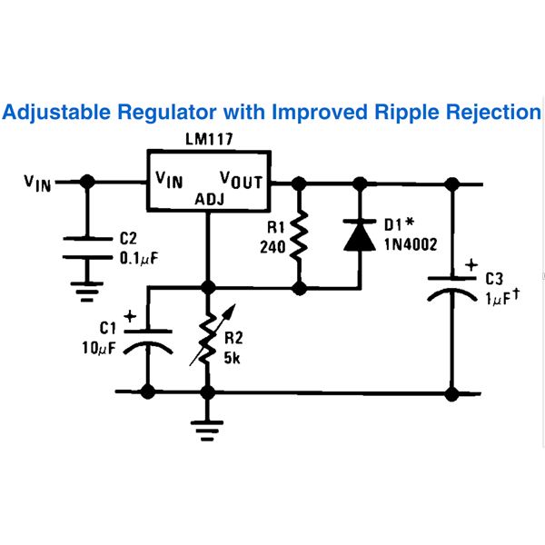
Adjustable Regulator with Improved Ripple Rejection
The figure shows a standard LM317 wiring layout used for obtaining variable output voltages from 1.2 to the maximum supply input. However the inclusion of C1, C3 and D1 helps to improve ripple rejection greatly and enhances the overall regulation of the circuit. C1 cancels out all possible ripple generations across R2 while it’s being operated and C3 filters out all residual ripple factors.LM317 Adjustable Regulator with Improved Ripple Rejection Circuit Diagram, Image
Slow Turn-On 15V Regulator
In this configuration the voltage is fixed and clamped at 15 volts through appropriate selections of R1and R2. The inclusion of an extra transistor R3 and C1 makes it sure that the output of the circuit turns ON gradually after an input supply is applied. The output switch ON period will depend on the value of R3 and C1. Increasing the values will produce higher time delays and vice versa. The feature ensures safe surge protected switch ON of the preceding electronic circuit, becomes ideally compatible with high power amplifiers where a slow turn ON of the speakers becomes very crucial for avoiding sudden dangerous voltage "pops" in the speakers during power switch ONs.LM317 Slow Turn-On 15V Regulator Circuit Diagram, Image
Power Follower
This is a very straightforward configuration using two ICs – the LM195 and LM317. As the name suggests the function of the circuit is to act as a regulated buffer and reproduce exactly the same power which is being applied at the free end of R1. The output obtained from this circuit is overload and short circuit protected.LM317 Power Follower Circuit Diagram, Image
5A Constant Voltage / Constant Current Regulator
An outstanding circuit can be built using LM317 IC along with Lm301 IC and a handful of other passive components. The parts wired around LM301 helps to generate variable outputs featuring constant voltage and constant current levels at the respective adjusted values. Voltage is varied through R8 while R2 takes hold of the current adjustment operations. The diodes are included for providing extra safety to the ICs. The power transistor MJ4502 in association with R1 and R3 act as current sensor and amplifier, with maximum current capacity of 5 Amps. For acquiring higher output currents, the transistor, R1 and R3 may be adjusted proportionately. The transistor may require a heatsink. Other equivalent values like TIP32C, MJE2955, etc. may also be tried in place of the shown transistor type.
The application is best suited for building high end type power supply units with excellent specifications and as battery chargers for charging all types of lead acid or SMF batteries.LM317, 5A Constant Voltage, Constant Current Regulator Circuit Diagram, Image
1A Current Regulator
The circuit is very simple yet promises huge application scope. As can be seen in the diagram the IC LM317 hardly incorporates any external components, just a couple of them (C1 and R1) to be precise. C1 ensures ripple filtration and smoothes the input DC. R1 is interestingly connected to the ADJ terminal of the IC so that its gets clamped with the released output current from the IC. This forces the IC’s internal circuitry to monitor and control the output current to a level determined by the value of R1. Here the value ensures that the output current cannot rise beyond 1 Amp. Other values can be appropriately and proportionately worked in place of R1 for getting other desired control levels of the output current.
As the circuit is protected from invalid current levels, it becomes suitable for applications where operations at strict or critical current levels become imperative. The circuit can be also be used for charging cell phone batteries (cell phones), automobile batteries, Ni-Cd batteries, for driving green pointer lasers, and for driving vulnerable high efficiency white LED lamps.
LM317, 1A Current Regulator Circuit Diagram, Image
5V Regulator with Electronic Shutdown
A very interesting modification in the standard LM317 circuit enables the circuit to monitor external dangerous situation and shut down the output of the regulator in response to the external relevant trigger. The circuit is configured to produce precise 5 volt output ideally suitable for all logic circuits (especially TTL circuits).
The selected values of R1 and R2 here fixes the output to the required 5V, R2 may be altered with other relevant values for acquiring other desired output voltages, though. The transistor has been included specifically for the shut-down operation. Under unfavorable conditions an external trigger switches the transistor into action which conducts and shorts R2 to instantly bring down the output to zero volts.
LM317 5V Logic Regulator with Electronic Shutdown Circuit Diagram, Image
Since the circuit is equipped with the feature of switching off through an external trigger, becomes extremely suitable for many critical circuit allplications where fool proof shut down facilities are felt to be an absolute necessity.
High Current Adjustable Regulator
This configuration also provides the usual regulated, stabilized variable voltage output using LM317, however here the current output is immensely increased and thus becomes suitable with circuits involve huge currents at desired settable voltages. The transistor (as explained for one of the above circuits) is incorporated for allowing high currents at the output irrespective of the adjusted voltage, a group of ICs LM195 has been stationed for monitoring the current with the help of R3 and makes sure it doesn’t fall below a particular threshold determined by the value of R3. The maximum amount of current can be set by appropriately dimensioning the value of R1.

Related Links
Downloads
LM317 Adjustable Power Supply - Link
|
|
|
| |
Accurate LC Meter
Build your own Accurate LC Meter (Capacitance Inductance Meter) and start making your own coils and inductors. This LC Meter allows to measure incredibly small inductances making it perfect tool for making all types of RF coils and inductors. LC Meter can measure inductances starting from 10nH - 1000nH, 1uH - 1000uH, 1mH - 100mH and capacitances from 0.1pF up to 900nF. The circuit includes an auto ranging as well as reset switch and produces very accurate and stable readings. |
|
PIC Volt Ampere Meter
Volt Ampere Meter measures voltage of 0-70V or 0-500V with 100mV resolution and current consumption 0-10A or more with 10mA resolution. The meter is a perfect addition to any power supply, battery chargers and other electronic projects where voltage and current must be monitored. The meter uses PIC16F876A microcontroller with 16x2 backlighted LCD. |
|
|
|
60MHz Frequency Meter / Counter
Frequency Meter / Counter measures frequency from 10Hz to 60MHz with 10Hz resolution. It is a very useful bench test equipment for testing and finding out the frequency of various devices with unknown frequency such as oscillators, radio receivers, transmitters, function generators, crystals, etc. |
|
1Hz - 2MHz XR2206 Function Generator
1Hz - 2MHz XR2206 Function Generator produces high quality sine, square and triangle waveforms of high-stability and accuracy. The output waveforms can be both amplitude and frequency modulated. Output of 1Hz - 2MHz XR2206 Function Generator can be connected directly to 60MHz Counter for setting precise frequency output. |
|
|
|
BA1404 HI-FI Stereo FM Transmitter
Be "On Air" with your own radio station! BA1404 HI-FI Stereo FM Transmitter broadcasts high quality stereo signal in 88MHz - 108MHz FM band. It can be connected to any type of stereo audio source such as iPod, Computer, Laptop, CD Player, Walkman, Television, Satellite Receiver, Tape Deck or other stereo system to transmit stereo sound with excellent clarity throughout your home, office, yard or camp ground. |
|
USB IO Board
USB IO Board is a tiny spectacular little development board / parallel port replacement featuring PIC18F2455/PIC18F2550 microcontroller. USB IO Board is compatible with Windows / Mac OSX / Linux computers. When attached to Windows IO board will show up as RS232 COM port. You can control 16 individual microcontroller I/O pins by sending simple serial commands. USB IO Board is self-powered by USB port and can provide up to 500mA for electronic projects. USB IO Board is breadboard compatible. |
|
|
|
|
ESR Meter / Capacitance / Inductance / Transistor Tester Kit
ESR Meter kit is an amazing multimeter that measures ESR values, capacitance (100pF - 20,000uF), inductance, resistance (0.1 Ohm - 20 MOhm), tests many different types of transistors such as NPN, PNP, FETs, MOSFETs, Thyristors, SCRs, Triacs and many types of diodes. It also analyzes transistor's characteristics such as voltage and gain. It is an irreplaceable tool for troubleshooting and repairing electronic equipment by determining performance and health of electrolytic capacitors. Unlike other ESR Meters that only measure ESR value this one measures capacitor's ESR value as well as its capacitance all at the same time. |
|
Audiophile Headphone Amplifier Kit
Audiophile headphone amplifier kit includes high quality audio grade components such as Burr Brown OPA2134 opamp, ALPS volume control potentiometer, Ti TLE2426 rail splitter, Ultra-Low ESR 220uF/25V Panasonic FM filtering capacitors, High quality WIMA input and decoupling capacitors and Vishay Dale resistors. 8-DIP machined IC socket allows to swap OPA2134 with many other dual opamp chips such as OPA2132, OPA2227, OPA2228, dual OPA132, OPA627, etc. Headphone amplifier is small enough to fit in Altoids tin box, and thanks to low power consumption may be supplied from a single 9V battery. |
|
|
|
|
|
Arduino Prototype Kit
Arduino Prototype is a spectacular development board fully compatible with Arduino Pro. It's breadboard compatible so it can be plugged into a breadboard for quick prototyping, and it has VCC & GND power pins available on both sides of PCB. It's small, power efficient, yet customizable through onboard 2 x 7 perfboard that can be used for connecting various sensors and connectors. Arduino Prototype uses all standard through-hole components for easy construction, two of which are hidden underneath IC socket. Board features 28-PIN DIP IC socket, user replaceable ATmega328 microcontroller flashed with Arduino bootloader, 16MHz crystal resonator and a reset switch. It has 14 digital input/output pins (0-13) of which 6 can be used as PWM outputs and 6 analog inputs (A0-A5). Arduino sketches are uploaded through any USB-Serial adapter connected to 6-PIN ICSP female header. Board is supplied by 2-5V voltage and may be powered by a battery such as Lithium Ion cell, two AA cells, external power supply or USB power adapter. |
|
200m 4-Channel 433MHz Wireless RF Remote Control
Having the ability to control various appliances inside or outside of your house wirelessly is a huge convenience, and can make your life much easier and fun. RF remote control provides long range of up to 200m / 650ft and can find many uses for controlling different devices, and it works even through the walls. You can control lights, fans, AC system, computer, printer, amplifier, robots, garage door, security systems, motor-driven curtains, motorized window blinds, door locks, sprinklers, motorized projection screens and anything else you can think of. |
|
|
|


