| |
XR2206 Function Generator |
|
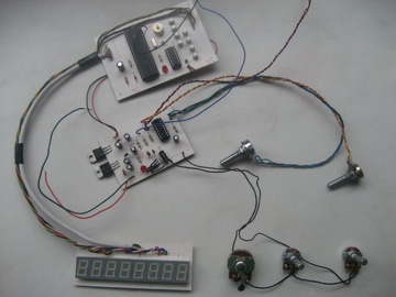
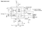
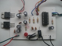
Presented here is XR2206 function generator with multiple waveform selection and a frequency readout display. The diagram on the right shows the internal workings of the XR2206 in the form of a block diagram. Essentially the chip contains A VCO (voltage controller oscillator), wave shaper and buffer. The
xr2206 frequency generator diagram frequency of the VCO is set with a capacitor and a resistor. The capacitor sets the frequency range whilst a variable resistor can be used to vary the frequency in the set range. The frequency is defined by ƒ = 1/(RC). For a starting point for the design of the frequency generator I used the test circuit from the XR2206 datasheet. I built this on bread board and experimented with the timing resistor and capacitor and managed to get the frequency up to 4MHz.
I eliminated things I didn’t need such as the FSK input and also R2 which is only needed for the FSK function. At this point I realized the square wave output is separate to the sine and triangle waves and is not fed through the wave shaping circuit or the output buffer. Since the amplitude is adjusted using the output buffer in the XR2206, the amplitude of the square wave cannot be adjusted along with the sine and triangle outputs. I realized the square wave output is for synchronization with other systems which I don’t think was clear in the datasheet. A separate op-amp would have to be used to control the amplitude of the square wave possibly using a potentiometer on the op-amp feedback to control the gain.
Setting frequency ranges The relationship between RC and the frequency is:
• Small R value and small C value = higher frequency
• Large R value and small C value = lower frequency
The datasheet quotes that the minimum and maximum values for R are 1K? and 2M?. The minimum and maximum values for C are 1nF and 100µF. Using a 2M? potentiometer and just two capacitors, a full frequency range from 0.01Hz to 1MHz can be achieved. From this information I realised there was no need to have four switchable frequency ranges as stated in the specification. Using just two frequency ranges (two capacitors) it proved quite difficult to accurately set the frequency to the desired value. I decided to have three ranges to cover 1Hz to 1MHz: low, medium and high to be set with three capacitors.
My calculations tell me the 3 following 3 capacitor values should work for a low, medium and high range:
Capacitor value Lower frequency Higher frequency Range
1µF 1 Hz 209 Hz Low
1000pF 170 Hz 20.1 KHz Medium
100pF 17 KHz 2 MHz High
As can be seen from the above table, the three frequency ranges overlap so the full range is covered effectively. In the high frequency range it became very difficult to accurately adjust the frequencies even with a fine adjust potentiometer. I decided to use another potentiometer of smaller value in series with the existing course and fine adjust potentiometers. I implemented a course, fine and ultra fine frequency adjust using three potentiometers of 1M?, 100K? and 1K? respectively. I used pin headers for the potentiometers switches so they can be connected with wires and chassis mounted onto an instrument case.
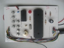
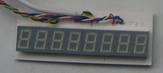
Frequency counter
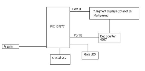
For the frequency display I used a frequency counter. I needed it to have a resolution of 1Hz and a range of up to at least 2MHz. This can be achieved with just one PIC chip with an appropriate program. The program will count the positive edges of the input signal every second (gate time = 1 second). The program will then determine the input frequency and send the value out to the display which is refreshed every second at the end of every gate time. I decided to use an LED display instead of an LCD display simply because i think it looks better and is also alot more robust and easier to read. As shown in the block diagram of the frequency counter (below) I used a 4017 decade counter to multiplex the display.
Building and testing the frequency counter
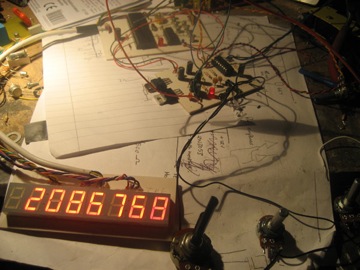
Frequency counters need to be accurate. To be able to calibrate my frequency counter I added a variable capacitor in place of the fixed capacitor in the PIC program 4MHz crystal clock. This in effect will let the gate time, which is derived from the program clock to be finely adjusted.
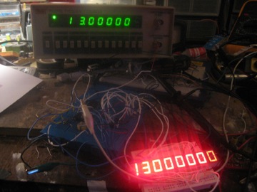
I used a very accurate OCXO (oven-controlled crystal oscillator) made for the purpose of calibrating frequency counting instruments. With a frequency of exactly 13MHz connected to the input of my frequency counter I was able to adjust my program clock using the variable capacitor until the display of my frequency counter read exactly 13MHz. See the picture below comparing my bench frequency counter and my project frequency counter both connected to the OCXO 13MHz oscillator:
accurate Spot on i'd say!
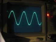
Combining the frequency generator and the frequency counter
The frequency counter somehow was interfering with the frequency generator output frequency. I suspect it could have been the program clock causing the interference. To overcome the problem I heavily decoupled the power supply inputs and outputs on the power supply, suppressing any noise or oscillations. After decoupling, the waveform had no visible distortion.
I used Eagle (Easily Applicable Graphical Layout Editor) produced by Cadsoft to design my PCBs. Once I designed the PCB layouts I used a ray-tracing package Povray (Persistence of Vision Ray tracer) to create 3D renders of my circuits that I had designed in Eagle.
Frequency Generator
Frequency Counter
Frequency Display
Full function generator with external controls to be chassis mounted.
Related Links
Downloads
XR2206 Function Generator - Link
|
|
|
| |
Accurate LC Meter
Build your own Accurate LC Meter (Capacitance Inductance Meter) and start making your own coils and inductors. This LC Meter allows to measure incredibly small inductances making it perfect tool for making all types of RF coils and inductors. LC Meter can measure inductances starting from 10nH - 1000nH, 1uH - 1000uH, 1mH - 100mH and capacitances from 0.1pF up to 900nF. The circuit includes an auto ranging as well as reset switch and produces very accurate and stable readings. |
|
PIC Volt Ampere Meter
Volt Ampere Meter measures voltage of 0-70V or 0-500V with 100mV resolution and current consumption 0-10A or more with 10mA resolution. The meter is a perfect addition to any power supply, battery chargers and other electronic projects where voltage and current must be monitored. The meter uses PIC16F876A microcontroller with 16x2 backlighted LCD. |
|
|
|
60MHz Frequency Meter / Counter
Frequency Meter / Counter measures frequency from 10Hz to 60MHz with 10Hz resolution. It is a very useful bench test equipment for testing and finding out the frequency of various devices with unknown frequency such as oscillators, radio receivers, transmitters, function generators, crystals, etc. |
|
1Hz - 2MHz XR2206 Function Generator
1Hz - 2MHz XR2206 Function Generator produces high quality sine, square and triangle waveforms of high-stability and accuracy. The output waveforms can be both amplitude and frequency modulated. Output of 1Hz - 2MHz XR2206 Function Generator can be connected directly to 60MHz Counter for setting precise frequency output. |
|
|
|
BA1404 HI-FI Stereo FM Transmitter
Be "On Air" with your own radio station! BA1404 HI-FI Stereo FM Transmitter broadcasts high quality stereo signal in 88MHz - 108MHz FM band. It can be connected to any type of stereo audio source such as iPod, Computer, Laptop, CD Player, Walkman, Television, Satellite Receiver, Tape Deck or other stereo system to transmit stereo sound with excellent clarity throughout your home, office, yard or camp ground. |
|
USB IO Board
USB IO Board is a tiny spectacular little development board / parallel port replacement featuring PIC18F2455/PIC18F2550 microcontroller. USB IO Board is compatible with Windows / Mac OSX / Linux computers. When attached to Windows IO board will show up as RS232 COM port. You can control 16 individual microcontroller I/O pins by sending simple serial commands. USB IO Board is self-powered by USB port and can provide up to 500mA for electronic projects. USB IO Board is breadboard compatible. |
|
|
|
|
ESR Meter / Capacitance / Inductance / Transistor Tester Kit
ESR Meter kit is an amazing multimeter that measures ESR values, capacitance (100pF - 20,000uF), inductance, resistance (0.1 Ohm - 20 MOhm), tests many different types of transistors such as NPN, PNP, FETs, MOSFETs, Thyristors, SCRs, Triacs and many types of diodes. It also analyzes transistor's characteristics such as voltage and gain. It is an irreplaceable tool for troubleshooting and repairing electronic equipment by determining performance and health of electrolytic capacitors. Unlike other ESR Meters that only measure ESR value this one measures capacitor's ESR value as well as its capacitance all at the same time. |
|
Audiophile Headphone Amplifier Kit
Audiophile headphone amplifier kit includes high quality audio grade components such as Burr Brown OPA2134 opamp, ALPS volume control potentiometer, Ti TLE2426 rail splitter, Ultra-Low ESR 220uF/25V Panasonic FM filtering capacitors, High quality WIMA input and decoupling capacitors and Vishay Dale resistors. 8-DIP machined IC socket allows to swap OPA2134 with many other dual opamp chips such as OPA2132, OPA2227, OPA2228, dual OPA132, OPA627, etc. Headphone amplifier is small enough to fit in Altoids tin box, and thanks to low power consumption may be supplied from a single 9V battery. |
|
|
|
|
|
Arduino Prototype Kit
Arduino Prototype is a spectacular development board fully compatible with Arduino Pro. It's breadboard compatible so it can be plugged into a breadboard for quick prototyping, and it has VCC & GND power pins available on both sides of PCB. It's small, power efficient, yet customizable through onboard 2 x 7 perfboard that can be used for connecting various sensors and connectors. Arduino Prototype uses all standard through-hole components for easy construction, two of which are hidden underneath IC socket. Board features 28-PIN DIP IC socket, user replaceable ATmega328 microcontroller flashed with Arduino bootloader, 16MHz crystal resonator and a reset switch. It has 14 digital input/output pins (0-13) of which 6 can be used as PWM outputs and 6 analog inputs (A0-A5). Arduino sketches are uploaded through any USB-Serial adapter connected to 6-PIN ICSP female header. Board is supplied by 2-5V voltage and may be powered by a battery such as Lithium Ion cell, two AA cells, external power supply or USB power adapter. |
|
200m 4-Channel 433MHz Wireless RF Remote Control
Having the ability to control various appliances inside or outside of your house wirelessly is a huge convenience, and can make your life much easier and fun. RF remote control provides long range of up to 200m / 650ft and can find many uses for controlling different devices, and it works even through the walls. You can control lights, fans, AC system, computer, printer, amplifier, robots, garage door, security systems, motor-driven curtains, motorized window blinds, door locks, sprinklers, motorized projection screens and anything else you can think of. |
|
|
|