| |
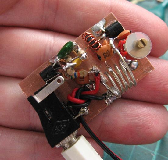
Here's a portable FM broadcast radio receiver for reception of FM broadcast band based around FET transistor. The topology is a classic grounded-gate FET VHF Hartley oscillator. The drain resonator inductance is centre-tapped with feedback to the source through a small capacitance. By tapping down towards the cold-end of the coil the feedback isn't as critical as your usual source-drain capacitor feedback and it tends to be far less difficult to get to work across a broad range of frequencies. The RFC to an RC source circuit to implement self-quenching is very traditional for super-regenerative detectors. The quench gets frequency-modulated somewhat by the drain current, so it varies with signal strength and the recovered modulation, this is typical for self-quenched circuits.
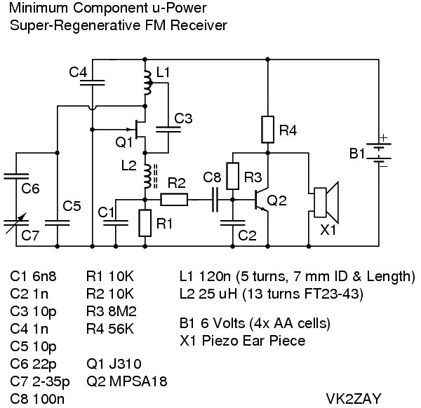
The detector alone provides sufficient audio to drive a crystal ear piece in a very quiet room, giving a true "single transistor" FM receiver. A largish resistor (~10 k) prevents the source circuit from seeing too much of the fairly large capacitance of the piezo element (about 14 nF) and pulling the quench well down into the audio range. Some additional audio volume can be achieved by redesigning the quench circuit to utilize the piezo capacitance directly, but the source resistance has to be dropped quite a lot to achieve a viable quench frequency and the gain in sensitivity isn't as fantastic as one might hope. Still, give it a try, a single active device FM radio, pulling < 100 uA is mighty impressive!
The detector can operate with the source resistance approaching 1 M, even at extremely feeble currents it is still very sensitive. Best over-all performance was achieved with 10 K and 6.8 nF in the source circuit.
I decided to add a stage of audio gain, retaining the use of a high impedance ear piece to keep the current consumption as small as possible. I picked a super-beta transistor, the MPSA18, for the audio amplifier, and used a simple self-bias topology. This was all to keep the total receiver current consumption very small and maximise the battery life. The audio quality is quite acceptable (the usual super-regen' slope-detection distortion and quench inter-modulation with stereo sub-carrier, etc). There is no volume control, the super-regenerative receiver has an AGC-like quality because of its physics. The audio power available is on the low side, it is for quiet environment listening only; not exactly library-quiet, but not the local pub on Friday evening either!
The complete receiver pulls around 500 uA from 6 volts. Four of your average bargain-store dry cells should run the receiver for at least a month continuously. Band-name alkaline cells might run it for a very long time indeed.
Tuning is achieved with a small alignment screwdriver, or similar insulated tool. The trimmer rotor is "grounded", but hand-capacitance is still slightly present because of the very high frequencies and gains involved (i.e. minor circuit layout strays).
Some effort was put into setting up the trimmer bandspread to cover the FM broadcast band (i.e. picking C5 and C6 to make C7 tune 88-108 MHz). I spent a lot of time doing the algebra to try to come up with a way to calculate the circuit stray capacitance and the actual tank inductance by trial frequency measurements with different fixed capacitances. The solution is truly horrible; involving finding a parabola that fits three points, which means solving a determinate of a 4x4 matrix equated to zero... I gave up after a few hours of wading through my sign and subscript mistakes, the whole experience leaving me feeling somewhat defeated!
I really wanted to achieve a result I could use to write a calculator, not unlike the VFO helper one which I did the "hard way" with pencil and paper as well. It would be extremely useful to be able to determine stray tank parameters just by measuring the frequency produced after a few capacitor swaps. I'll revisit this I think. Anyway, the geometry of the coil (7 mm diameter and length) gives about 120 nH using the Wheeler formula, and my inductance meter agrees. Some empirical capacitor swapping and trimmer jig twiddling later I arrived at a bandset (C5) of 10 pF and bandspread (C6) of 22 pF, giving a tuning range of 86-110 MHz, give or take. The stray capacitance that fits this is around 4.5 pF if I've done the math right. For comparison, my capacitance meter says the detector drain looks like 21.8 pF, but that is without a drain current, having the inductance disconnected, being measured at AF, etc... I'm happy, it tunes the whole band well.
Notes
Component substitution: The J310 is obsolete, I just happen to have a lot of them. Any RF FET should be a suitable replacement. The MPF102 is quite suitable. The MPSA18 could be replaced by any NPN signal transistor if you don't mind burning a bit more current. I'd recommend a low-noise device with good gain like the BC549C or BC550C. You'll obviously need to experiment (calculate) new resistor values for the audio stage if you change the transistor, the circuit is not particularly Β independent.
You might like to play with the quench frequency by altering R1 and C1. The selectivity is at a minimum 4 times the quench frequency. Lower quench frequencies become audible and will mix down higher signal components. If you want to place the quench below 15 kHz you'll need to add much better filtering, perhaps a Sallen Key filter or two. Higher quench frequencies reduce the gain somewhat, so pushing it too high is a bad idea. The FM stereo MPX signal has energy to around 56 kHz, more if there are SCA services. Typically the quench is set around 30 kHz (8 kHz into the lower L-R sideband), but as discussed it will vary with signal strength and the modulation. The quench will tend to mix down the L-R sidebands and/or beat with the pilot tone at 19kHz. The result can be absolutely horrible to listen to, especially when the quench is getting pulled around by the modulation or the L-R sidebands are especially intense (lots of stereo difference content). For purely mono signals the recovered audio can be reasonably high fidelity if you position the slope properly. For AM signals (i.e. The Airband) the receiver is especially affective.
L2 is not especially critical, it is just an RFC to isolate the RF signal at the source from being shunted by the quench oscillation capacitor. Anything that gives > j1 kΩ of reactance should be fine, so 1.6 uH or more is sufficient, perhaps a little less would still work. The 10 pF feedback capacitor is about -j160 Ω at 100 MHz, anything at least 5-10 times larger in magnitude than that should be fine. The RFC specified has about j15 kΩ of reactance. A few turns on a ferrite bead will work, as will an RFC wound on a high-value resistor. Just make sure the inductor's self-resonant frequency is far above the frequency of interest so it is still inductive. It is difficult to make an inductor too large at VHF that would upset the circuit that isn't already looking very capacitive.
L1 and the associated C5,C6,C7 capacitors can be changed to put the receiver anywhere you like from high-HF to low-UHF. My particular receiver topped-out at 235 MHz with the 120 nH coil (indicating a stray capacitance of around 4 pF which is in reasonable agreement with the bandspread capacitor calculations), but could go much higher with smaller inductances.
Putting the radio on 10 metres is an interesting idea, it isn't especially difficult to build a miniature AM transceiver using this as the receiver, if you had enough poles on your TR switch/relay you could use the same transistor for the TX and RX, even the same tank. Similar ideas were explored years ago when frequency stability standards weren't what they are now. I've seen articles describing construction of 2 metre HTs using pairs of nuvistors or acorn tubes with free-running LC oscillators on TX and RX, switching around the cathode circuit to achieve either super-regeneration for RX or plate-modulated smooth oscillation for TX.
Related Links
Downloads
FM Broadcast Receiver - Link
|
|
|
| |
Accurate LC Meter
Build your own Accurate LC Meter (Capacitance Inductance Meter) and start making your own coils and inductors. This LC Meter allows to measure incredibly small inductances making it perfect tool for making all types of RF coils and inductors. LC Meter can measure inductances starting from 10nH - 1000nH, 1uH - 1000uH, 1mH - 100mH and capacitances from 0.1pF up to 900nF. The circuit includes an auto ranging as well as reset switch and produces very accurate and stable readings. |
|
PIC Volt Ampere Meter
Volt Ampere Meter measures voltage of 0-70V or 0-500V with 100mV resolution and current consumption 0-10A or more with 10mA resolution. The meter is a perfect addition to any power supply, battery chargers and other electronic projects where voltage and current must be monitored. The meter uses PIC16F876A microcontroller with 16x2 backlighted LCD. |
|
|
|
60MHz Frequency Meter / Counter
Frequency Meter / Counter measures frequency from 10Hz to 60MHz with 10Hz resolution. It is a very useful bench test equipment for testing and finding out the frequency of various devices with unknown frequency such as oscillators, radio receivers, transmitters, function generators, crystals, etc. |
|
1Hz - 2MHz XR2206 Function Generator
1Hz - 2MHz XR2206 Function Generator produces high quality sine, square and triangle waveforms of high-stability and accuracy. The output waveforms can be both amplitude and frequency modulated. Output of 1Hz - 2MHz XR2206 Function Generator can be connected directly to 60MHz Counter for setting precise frequency output. |
|
|
|
BA1404 HI-FI Stereo FM Transmitter
Be "On Air" with your own radio station! BA1404 HI-FI Stereo FM Transmitter broadcasts high quality stereo signal in 88MHz - 108MHz FM band. It can be connected to any type of stereo audio source such as iPod, Computer, Laptop, CD Player, Walkman, Television, Satellite Receiver, Tape Deck or other stereo system to transmit stereo sound with excellent clarity throughout your home, office, yard or camp ground. |
|
USB IO Board
USB IO Board is a tiny spectacular little development board / parallel port replacement featuring PIC18F2455/PIC18F2550 microcontroller. USB IO Board is compatible with Windows / Mac OSX / Linux computers. When attached to Windows IO board will show up as RS232 COM port. You can control 16 individual microcontroller I/O pins by sending simple serial commands. USB IO Board is self-powered by USB port and can provide up to 500mA for electronic projects. USB IO Board is breadboard compatible. |
|
|
|
|
ESR Meter / Capacitance / Inductance / Transistor Tester Kit
ESR Meter kit is an amazing multimeter that measures ESR values, capacitance (100pF - 20,000uF), inductance, resistance (0.1 Ohm - 20 MOhm), tests many different types of transistors such as NPN, PNP, FETs, MOSFETs, Thyristors, SCRs, Triacs and many types of diodes. It also analyzes transistor's characteristics such as voltage and gain. It is an irreplaceable tool for troubleshooting and repairing electronic equipment by determining performance and health of electrolytic capacitors. Unlike other ESR Meters that only measure ESR value this one measures capacitor's ESR value as well as its capacitance all at the same time. |
|
Audiophile Headphone Amplifier Kit
Audiophile headphone amplifier kit includes high quality audio grade components such as Burr Brown OPA2134 opamp, ALPS volume control potentiometer, Ti TLE2426 rail splitter, Ultra-Low ESR 220uF/25V Panasonic FM filtering capacitors, High quality WIMA input and decoupling capacitors and Vishay Dale resistors. 8-DIP machined IC socket allows to swap OPA2134 with many other dual opamp chips such as OPA2132, OPA2227, OPA2228, dual OPA132, OPA627, etc. Headphone amplifier is small enough to fit in Altoids tin box, and thanks to low power consumption may be supplied from a single 9V battery. |
|
|
|
|
|
Arduino Prototype Kit
Arduino Prototype is a spectacular development board fully compatible with Arduino Pro. It's breadboard compatible so it can be plugged into a breadboard for quick prototyping, and it has VCC & GND power pins available on both sides of PCB. It's small, power efficient, yet customizable through onboard 2 x 7 perfboard that can be used for connecting various sensors and connectors. Arduino Prototype uses all standard through-hole components for easy construction, two of which are hidden underneath IC socket. Board features 28-PIN DIP IC socket, user replaceable ATmega328 microcontroller flashed with Arduino bootloader, 16MHz crystal resonator and a reset switch. It has 14 digital input/output pins (0-13) of which 6 can be used as PWM outputs and 6 analog inputs (A0-A5). Arduino sketches are uploaded through any USB-Serial adapter connected to 6-PIN ICSP female header. Board is supplied by 2-5V voltage and may be powered by a battery such as Lithium Ion cell, two AA cells, external power supply or USB power adapter. |
|
200m 4-Channel 433MHz Wireless RF Remote Control
Having the ability to control various appliances inside or outside of your house wirelessly is a huge convenience, and can make your life much easier and fun. RF remote control provides long range of up to 200m / 650ft and can find many uses for controlling different devices, and it works even through the walls. You can control lights, fans, AC system, computer, printer, amplifier, robots, garage door, security systems, motor-driven curtains, motorized window blinds, door locks, sprinklers, motorized projection screens and anything else you can think of. |
|
|
|