| |
Adjustable Bench Power Supply |
|
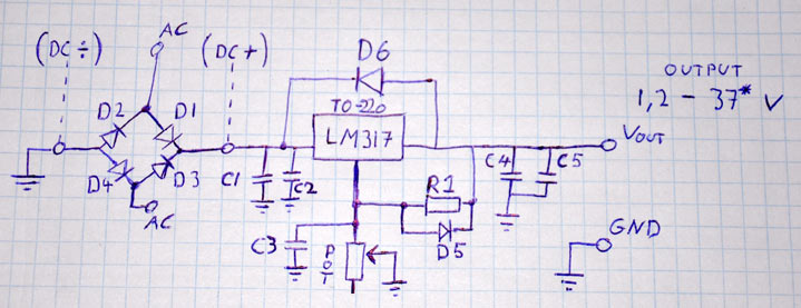
If you are starting to learn electronics variable bench power supply is the first thing you should build to power your projects. This simple power supply is built around the LM317/LM338/LM350 linear voltage regulator. The LM317 is one of the most popular voltage regulators on the market, and for good reason. It is very simple to use and requires very few external components. LM317/LM338/LM350 regulators provide a stable and reliable output voltage adjustable between 1.25V and 37V. The short circuit protection is also built right in the voltage regulator.
Component List:
1x Voltage Regulator, LM317/LM338/LM350 or similar.
1x Mains Transformer, rated for your desired output voltage and current (I used a 24 v (12-0-12 v), 50 VA transformer to give me 24 v and 1.5 amps output)
(Alternative, use a AC to DC wall adapter rated for min. 4-5 volts above your output. And rated a good deal above your desired max current. But i highly recommend a transformer)
1x Electrolytic Capacitor 4700 uF 50v (2200 uF may do below 1 amp output, and the voltage rating should be above your rectified DC input voltage).
1x Potentiometer 5k to 10k Ohm (10 turn potentiometer hardly recommended!)
2x Electrolytic Capacitors 2.2 uF 50v (up to 10 uF will be fine, and the voltage rating should be above your max output voltage)
1x Ceramic or film capacitor (100 to 250 nF at 50 V or higher. This capacitor is optional)
1x Resistor (Value depended upon the value of your potentiometer and your desired max output voltage)
4x 1N5402 Diode (Or any rectifying diode with a voltage and current rating well above what your supply will be capable of delivering)
2x 1N4002 or similar.
2x Output terminals, red and black (Binding posts preferred)
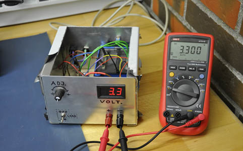
1x Panel meter (Analog or digital, for reading the output voltage)
1x Housing - Copy my design, design your own or use any case of your choice.
1x Heat sink, approx 5.5x7x12 cm for a 1.5 amp output, but read the description later on. (I used a smaller heatsink, but added a fan)
1x Mains switch
1x Fuse holder + fuse (fuse depends on your transformer, output current and your mains voltage. You will have to calculate the value)
1x Load switch, to toggle your output on and off.
1x Transformer switch, only if your transformer have multiple tabs like mine (explained later).
Wire - standard equipment wire + some heavy wire that will handle your max current
Heat shrink tubing
Your standard soldering equipment - soldering iron, solder, flux etc.
Let's get started!
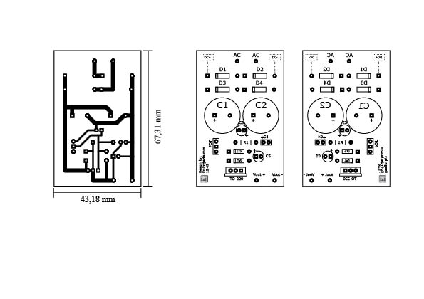
Download the schematic and PCB layout files at the bottom of the page. Print out the layout and etch the board, or use the schematic and make your own layout. You can use prototyping board if you like, or if you don't have the tools to make your own boards (A tutorial is coming on how to do that! Alt. Check YouTube for DIY PCB manufacturing). If you want the heat sink on the board, remember to take this in to a count when you cut the board.
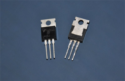
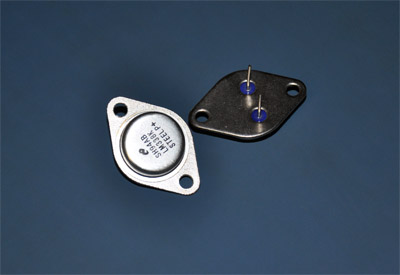
Choose your regulator. If you have no idea what to go for, pick the LM317, in a "TO-220 Package", this will give you 1.5 amps of output current which is enough for 95 % of electronics work. You can also choose a more expensive LM338K in a "TO-3 Package" that will give you 5 amps of output current which is a huge overkill in most cases, but necessary if you work on that kind of levels, but if you are a beginner I'll recommend the LM317.
The TO-3 package is ideal for dissipating the heat generated by high current applications, that's its major advantage over the TO-220 which is great for lower currents. On the other hand the TO-220 has the advantage of a much smaller size which can easily be soldered to a PCB.
Note that the maximum heat in watts generated by your regulator is equal to the difference between the input DC voltage and the minimum output voltage (1.25v) times the output current.
Example
24v in - 1,25v out = a difference of 22,75 v
22,75v x 1.5 amp = 34,125 watts needs to be dissipated at max.
But the regulator has an overload protection that will limit the current in order to hold the power dissipation below a threshold. A LM317 will be limited to about 1.25 amps at the voltages in the above example, according to the datasheet. If you want the full current output at 1.25 volts you have to lower the input voltage, read about transformers below!
You will need to calculate this when choosing your heat sink (if you use the LM317 you can just use the heat sink I specified in the materials list).
In the datasheet for the heat sink a value is specified saying how many degrees the temp. of the heat sink will rise pr. watt you put into it. Times this with your calculated value from above and remember to add the room temp. when done. Your final value should not exceed 80c.
By forcing air through the heat sink you can lower the temp. significantly.
For the transformer, it is very important to choose a transformer rated for your mains voltage on the primary side (120 or 240 VAC), The secondary side should be rated according to your desired output voltage. Some transformers have multiple tabs on the secondary side and for a 24 v transformer it may be written like this 12-0-12, this means you can either get the full voltage by measuring between the two 12v wires or half the voltage by measuring between 0 and one of the two 12v wires. For our purpose this is great because we can, by adding a switch, lower the input voltage to our regulator when we work with lower voltages, and get the full voltage when we work on those higher voltage circuits. We want to do this because the lower the input voltage is, compared to the output voltage the lower the heat generated by the regulator. This means we can get away with a smaller heat sink. You can still use a transformer without this feature though, your heat sink just have to be bigger.
Note that your rectified DC voltage will be roughly 1.4 times of your transformers rated AC RMS voltage when rectified. And due to the voltage drop over the diodes and the regulator in the circuit you will need an extra 4 volts of DC input voltage compared to the output.
If you get all confused by this, choose a transformer rated for 22 to 24 volts AC on the secondary side, to give you about 24 to 30 volts DC on the output of your supply. And a rated power of 50 VA or more will be fine for your LM317.
If you are not 100% confident in working with mains wiring you should not use a transformer that do not come with a mains plug. The majority of transformers will not and these have to be soldered in, and those that do come with a plug are rather expensive. There is no point in taking the risk of killing yourself in the process, should you do something wrong.
Instead, go for a standard wall adapter with a DC output rated for 4-5 volts above your desired supply-output voltage and depending on the brand, it should be around 20 % higher rated in current than what you need.
For your adjustment of the voltage, you need a potentiometer. We need to calculate the value unfortunately, but it is very easy.
You can use a few different types of potentiometers: single turn, ten turn or a multi-turn trimmer potentiometer.
The single turn pot is cheap, but not recommended as you will get a very coarse adjustment. setting a value precise on one of these is NOT easy and it will annoy you very soon. But you can though, put two in series, a large value and a small value, to give you a fine and a coarse adjustment. Connect them like this:
The 10 turn pot is the clear winner, but more expensive. It will give you a fine resolution, where you can easily set the voltage within 10 mV of accuracy.
A trick to save a bit of money is to buy a multi-turn trimmer pot (10 or 15 turns), and glue a shaft onto the adjustment screw with steel epoxy. This is not the best way though, because the trimmer pots are not made for long term durability. 'And they do also have a bit of play in them. But i have used this method before, and it works reasonably well.
To calculate the values for the potentiometer and the resistor R1, use this formula: Volt-out = 1.25*(1+R2/R1)
Where R2 is the value of your potentiometer, and volt-out is the max voltage you want to be able to set (this will also be limited by your transformer).
You should always choose a volt-out a little higher then what you want, to take the tolerances of the pot and resistors in to a count.
For some easy values with a 5k ohm potentiometer you will need the following value for R1:
if R1 = 200 ohm Volt-out max = 32,5 v
if R1 = 220 ohm Volt-out max = 29,65 v
if R1 = 250 ohm Volt-out max = 26,5 v
if R1 = 270 ohm Volt-out max = 24,39 v
if R1 = 300 ohm Volt-out max = 22,08 v
If you use a 10k ohm pot just double the value of R1 for the same voltage output. But note that the value of R1 should not exceed 357 ohms. If it does, the regulator might not be able to go to low voltages with nothing connected to the output.
Solder the components to the board, following the schematic or component overlay, with wires coming out to the potentiometer, AC input, and the output.
If you use a AC to DC wall adapter, you can leave out diodes D1, D2, D3 and D4, and solder the DC wires to the holes marked DC+ and DC- , measure the voltage coming of the adapter with your multimeter to make sure you get the polarity correct. But this is ONLY if you have a DC input. If you use an AC source (ie. transformer) you ignore the DC+ and DC- markings and follow the original schematic / component overlay.
(CAUTION: If you connect AC across DC+ and DC- the whole board will go up in smoke with a loud bang, and that is considered a bad thing! So be careful here if you are new to this stuff ;-] )
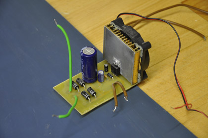
If you use a TO-3 type regulator you will need wires to connect this also, solder them into the TO-220 pads and be careful not to make any wires touch each other! If you use the TO-220 type as the board is designed for, you can either solder it in directly if you want the heat sink attached to the board, or solder in the above mentioned wiring if you want the heat sink separate.
Important: Make sure to mount the heat sink firmly to the board before you screw the TO-220 regulator onto it to avoid cracking the solder joints! Do not do like me and attach the heat sink to the regulator only. ;) My excuse is that I made this as my first power supply long ago, and just recently designed a new case for it ;)
There are two footprints for input filter capacitors (C1 and C2), so you can either use two smaller sized ones or one larger. I specified a 4700 uF in the materials list this will be good for a LM317, but ideally you would want as much input capacitance as possible. You can never have too much input capacitance! :D
What these capacitors will do is very simple and easy to understand. It takes your rectified input voltage coming of the bridge rectifier diodes, and smooths it out.
What is happening is charging and discharging of the capacitor(s).
If you draw a constant current form your supply, your load will discharge the caps in a fixed time period, but you charge the caps meanwhile by applying pulse current to them by the "rectified" signal you saw above.
Since the caps will only charge when the voltage of the "rectified" signal is higher than the voltage in the actual caps, you see these ramps, or what is called ripple, at 100 hz (in Europe at least, that will be 120 hz some places).
The higher the current you draw the faster you discharge the capacitors meaning larger ripple. But also, by increasing your capacity you lower the ripple, because they will take longer to discharge, and still being charged at the same frequency.
Most of this ripple is taken away by the regulator anyway, but a tiny bit will get through to the output. The main concern is, that your max stable output will be a few volts under the lower peak of your ripple. Say you got 32 volts input like I did, but instead of 0,5 v ripple you have got 10 v ripple (a bit extreme, yes), this means your max output would be under 20 v compared to maybe around 28 v with the lower ripple of 0.5 v.
My advise: Get ENOUGH input capacitance, caps aren't that expensive !
Before soldering the electrolytic capacitors, make sure you got the polarity right. The negative terminal will be marked on the capacitor.
The same applies to the diodes, where the cathode is marked.
Now solder the wires where they belong, you may want to install everything in the case first.
Because the key is to get the output wires as short as possible, so try to mount the board close to the terminals.
You want your negative output to go directly to the negative terminal. But the positive output should go to the load switch, then from the other side of the switch to the positive terminal. Use thick wire that is rated for higher current than you need. While you're at it, solder an extra wire to the hot side of the load switch, in other words this wire should not be turned off by the switch. This wire can be thin because it is only for measuring the output voltage with your panel meter. Connect this wire with your sense input on your digital meter, or the positive input on your analog meter.
Connect your potentiometer. There are different pin outs for different potentiometers, so i suggest you measure the resistance between the terminals while the pot is turned all the way down (anti clockwise). The two terminals with a few ohms (if any) resistance will be the ones you use. Solder these two, to the pads marked POT on the board (note that only the upper two pads are in use on the board), which goes to where does not matter, but if you want it "correct" solder the wiper to the round pad, and the other wire to the square pad.
We leave the last terminal of the pot unconnected. (but some may argue it should be connected to GND. You can do this if you feel for it, but only if you got the above wiring "correct". )
The AC input to the board should be soldered to the transformers secondary side. If you have a transformer with a split secondary winding you can add a switch in between to change the voltage going to the board. This has to be an ON-ON type switch, meaning in one position pin 1 will be connected to pin 2 and in the other position pin 3 will be connected to pin 2. There are two different ways a split transformer can work. You have either three or four pins / wires coming out of it. This wont make a difference in this case. In the drawing below type 1 is the three wire type, and type 2 is the four wire type. We need a type 1 in this case, but you can turn a type 2 into a type 1 simply by soldering the two wires together.
The transformer should be labeled which wires are what, and you don't want to connect any of these wrong! And do be careful when working with transformers, there is a lot of power in these things!
Connect the mains wires to the primary side of the transformer with a switch and a fuse holder in series as shown above. Use a fuse holder designed for mains!
Use a popper rubber protection ring where the mains wire penetrates the case to avoid the cable being cut over time by the edge. Also make sure you can not push or pull the cable in or out of the box. Either clamp it to the case, or add stops both to the inside and outside of the case.
Heat shrink ALL mains wires so no bare copper or connections are present!
The fuse value can be calculated by dividing the VA rating of the transformer by the RMS voltage of your mains. In my case 100 VA / 230 V = 0,435 Amps, or what's equal to 435 mA. I used a 315 mA fuse since i know my power supply will not draw this much current anyway.
As said before, if you don't want to play around with mains wires, which you should not if you are unsure about any small detail. You can use a AC to DC wall adapter. Solder the wires to DC+ and DC-. Again double check your polarity.
Related Links
Downloads
Adjustable Bench Power Supply - Link
|
|
|
| |
Accurate LC Meter
Build your own Accurate LC Meter (Capacitance Inductance Meter) and start making your own coils and inductors. This LC Meter allows to measure incredibly small inductances making it perfect tool for making all types of RF coils and inductors. LC Meter can measure inductances starting from 10nH - 1000nH, 1uH - 1000uH, 1mH - 100mH and capacitances from 0.1pF up to 900nF. The circuit includes an auto ranging as well as reset switch and produces very accurate and stable readings. |
|
PIC Volt Ampere Meter
Volt Ampere Meter measures voltage of 0-70V or 0-500V with 100mV resolution and current consumption 0-10A or more with 10mA resolution. The meter is a perfect addition to any power supply, battery chargers and other electronic projects where voltage and current must be monitored. The meter uses PIC16F876A microcontroller with 16x2 backlighted LCD. |
|
|
|
60MHz Frequency Meter / Counter
Frequency Meter / Counter measures frequency from 10Hz to 60MHz with 10Hz resolution. It is a very useful bench test equipment for testing and finding out the frequency of various devices with unknown frequency such as oscillators, radio receivers, transmitters, function generators, crystals, etc. |
|
1Hz - 2MHz XR2206 Function Generator
1Hz - 2MHz XR2206 Function Generator produces high quality sine, square and triangle waveforms of high-stability and accuracy. The output waveforms can be both amplitude and frequency modulated. Output of 1Hz - 2MHz XR2206 Function Generator can be connected directly to 60MHz Counter for setting precise frequency output. |
|
|
|
BA1404 HI-FI Stereo FM Transmitter
Be "On Air" with your own radio station! BA1404 HI-FI Stereo FM Transmitter broadcasts high quality stereo signal in 88MHz - 108MHz FM band. It can be connected to any type of stereo audio source such as iPod, Computer, Laptop, CD Player, Walkman, Television, Satellite Receiver, Tape Deck or other stereo system to transmit stereo sound with excellent clarity throughout your home, office, yard or camp ground. |
|
USB IO Board
USB IO Board is a tiny spectacular little development board / parallel port replacement featuring PIC18F2455/PIC18F2550 microcontroller. USB IO Board is compatible with Windows / Mac OSX / Linux computers. When attached to Windows IO board will show up as RS232 COM port. You can control 16 individual microcontroller I/O pins by sending simple serial commands. USB IO Board is self-powered by USB port and can provide up to 500mA for electronic projects. USB IO Board is breadboard compatible. |
|
|
|
|
ESR Meter / Capacitance / Inductance / Transistor Tester Kit
ESR Meter kit is an amazing multimeter that measures ESR values, capacitance (100pF - 20,000uF), inductance, resistance (0.1 Ohm - 20 MOhm), tests many different types of transistors such as NPN, PNP, FETs, MOSFETs, Thyristors, SCRs, Triacs and many types of diodes. It also analyzes transistor's characteristics such as voltage and gain. It is an irreplaceable tool for troubleshooting and repairing electronic equipment by determining performance and health of electrolytic capacitors. Unlike other ESR Meters that only measure ESR value this one measures capacitor's ESR value as well as its capacitance all at the same time. |
|
Audiophile Headphone Amplifier Kit
Audiophile headphone amplifier kit includes high quality audio grade components such as Burr Brown OPA2134 opamp, ALPS volume control potentiometer, Ti TLE2426 rail splitter, Ultra-Low ESR 220uF/25V Panasonic FM filtering capacitors, High quality WIMA input and decoupling capacitors and Vishay Dale resistors. 8-DIP machined IC socket allows to swap OPA2134 with many other dual opamp chips such as OPA2132, OPA2227, OPA2228, dual OPA132, OPA627, etc. Headphone amplifier is small enough to fit in Altoids tin box, and thanks to low power consumption may be supplied from a single 9V battery. |
|
|
|
|
|
Arduino Prototype Kit
Arduino Prototype is a spectacular development board fully compatible with Arduino Pro. It's breadboard compatible so it can be plugged into a breadboard for quick prototyping, and it has VCC & GND power pins available on both sides of PCB. It's small, power efficient, yet customizable through onboard 2 x 7 perfboard that can be used for connecting various sensors and connectors. Arduino Prototype uses all standard through-hole components for easy construction, two of which are hidden underneath IC socket. Board features 28-PIN DIP IC socket, user replaceable ATmega328 microcontroller flashed with Arduino bootloader, 16MHz crystal resonator and a reset switch. It has 14 digital input/output pins (0-13) of which 6 can be used as PWM outputs and 6 analog inputs (A0-A5). Arduino sketches are uploaded through any USB-Serial adapter connected to 6-PIN ICSP female header. Board is supplied by 2-5V voltage and may be powered by a battery such as Lithium Ion cell, two AA cells, external power supply or USB power adapter. |
|
200m 4-Channel 433MHz Wireless RF Remote Control
Having the ability to control various appliances inside or outside of your house wirelessly is a huge convenience, and can make your life much easier and fun. RF remote control provides long range of up to 200m / 650ft and can find many uses for controlling different devices, and it works even through the walls. You can control lights, fans, AC system, computer, printer, amplifier, robots, garage door, security systems, motor-driven curtains, motorized window blinds, door locks, sprinklers, motorized projection screens and anything else you can think of. |
|
|
|