| |
Simple 88MHz-110MHz FM Transmitter |
|
This project will demonstrate how a simple 88MHz-110MHz FM transmitter can be built using very few parts and just one transistor. The transmitter can be attached to just about any electronic circuit to transmit information (both analog and digital), to create spy bugs, simple satellite circuits, and even radio coms.

How Does the FM Transmitter Work?
The circuit has three main stages, the input stage, the modulation stage, and the output. The input stage consists of capacitors C3 and C1, and resistor R1. Input signals into the FM transmitter must not contain a DC component as it would adversely affect the modulation/oscillation stage (by saturating the transistor) and therefore no FM signal would be generated. C3 is used to couple the input signal so that no DC component is fed into the transmitter. R1 provides biasing for the transistor by feeding a small amount of current into the base (which prevents the transistor from turning off).
The next stage is the modulation/oscillation stage which provides a carrier signal which is then modulated by the input signal. The oscillator consists of C2, L1, C4 and R2 with the frequency of oscillation being determined by C2 and L1 only. When power is applied to the circuit, a rush of current flows through the inductor. This rush of current will also pass through C4 via capacitive coupling which will result in current flowing through R2. Current flowing through R2 will result in a voltage drop across R2 and since R2 is connected to the emitter of Q1, the same voltage will be present on the emitter of Q1. This increase in voltage on the emitter therefore results in a smaller value of Vbe and this reduction in Vbe reduces the conduction of Q1. As C4 begins to charge the amount of current flowing through C4 reduces which results in less current flowing through R2. When this happens the voltage across R2 reduces which increases the size of Vbe and therefore increases the conduction of Q1. This increase in conduction results in C4 discharging and the whole cycle starting all over again.
Modulation is achieved thanks to parasitic capacitances inherent in BJT transistors. Between the base and emitter, base and collector, and collector and base, are parasitic capacitances whose capacitance value depends on the base current. By altering the base current these values change as well and since the oscillation in the circuit is dependent on all capacitors and inductors in the LC tank, the parasitic capacitances also affect the frequency of oscillation. Therefore, by changing the base current you change the frequency of the oscillation which is how the FM (frequency modulation) signal is produced.
Emitting the FM signal is done by AE1 which is a long piece of wire. The modulated signal is fed into the antenna which helps to transmit the EM waves generated by the current as it oscillates.
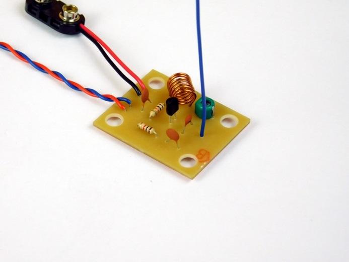
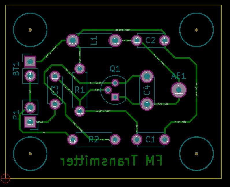
Construction
Building the circuit is very easy and can be done using either stripboard, breadboard, or even a PCB. The inductor L1 consists of 6 turns evenly spaced using thick copper wire (approximately 1mm in diameter) where the inductor has an overall diameter of 6mm.
Using Your FM Transmitter
Using the FM transmitter is fairly easy providing that an external FM receiver is available. Start by choosing an FM frequency on the radio that is empty (to ensure that your transmitter does not interfere with other stations). Then, feed a signal into the FM transmitter such as the audio output of an MP3 player or an electret microphone circuit. Using a plastic or other non-conductive implement, slowly tune C2 until the signal fed into the transmitter can be heard on the radio. At that point, the transmitter is broadcasting on the frequency selected on the radio
Related Links
Downloads
Simple 88MHz-110MHz FM Transmitter - Link
|
|
|
| |
Accurate LC Meter
Build your own Accurate LC Meter (Capacitance Inductance Meter) and start making your own coils and inductors. This LC Meter allows to measure incredibly small inductances making it perfect tool for making all types of RF coils and inductors. LC Meter can measure inductances starting from 10nH - 1000nH, 1uH - 1000uH, 1mH - 100mH and capacitances from 0.1pF up to 900nF. The circuit includes an auto ranging as well as reset switch and produces very accurate and stable readings. |
|
PIC Volt Ampere Meter
Volt Ampere Meter measures voltage of 0-70V or 0-500V with 100mV resolution and current consumption 0-10A or more with 10mA resolution. The meter is a perfect addition to any power supply, battery chargers and other electronic projects where voltage and current must be monitored. The meter uses PIC16F876A microcontroller with 16x2 backlighted LCD. |
|
|
|
60MHz Frequency Meter / Counter
Frequency Meter / Counter measures frequency from 10Hz to 60MHz with 10Hz resolution. It is a very useful bench test equipment for testing and finding out the frequency of various devices with unknown frequency such as oscillators, radio receivers, transmitters, function generators, crystals, etc. |
|
1Hz - 2MHz XR2206 Function Generator
1Hz - 2MHz XR2206 Function Generator produces high quality sine, square and triangle waveforms of high-stability and accuracy. The output waveforms can be both amplitude and frequency modulated. Output of 1Hz - 2MHz XR2206 Function Generator can be connected directly to 60MHz Counter for setting precise frequency output. |
|
|
|
BA1404 HI-FI Stereo FM Transmitter
Be "On Air" with your own radio station! BA1404 HI-FI Stereo FM Transmitter broadcasts high quality stereo signal in 88MHz - 108MHz FM band. It can be connected to any type of stereo audio source such as iPod, Computer, Laptop, CD Player, Walkman, Television, Satellite Receiver, Tape Deck or other stereo system to transmit stereo sound with excellent clarity throughout your home, office, yard or camp ground. |
|
USB IO Board
USB IO Board is a tiny spectacular little development board / parallel port replacement featuring PIC18F2455/PIC18F2550 microcontroller. USB IO Board is compatible with Windows / Mac OSX / Linux computers. When attached to Windows IO board will show up as RS232 COM port. You can control 16 individual microcontroller I/O pins by sending simple serial commands. USB IO Board is self-powered by USB port and can provide up to 500mA for electronic projects. USB IO Board is breadboard compatible. |
|
|
|
|
ESR Meter / Capacitance / Inductance / Transistor Tester Kit
ESR Meter kit is an amazing multimeter that measures ESR values, capacitance (100pF - 20,000uF), inductance, resistance (0.1 Ohm - 20 MOhm), tests many different types of transistors such as NPN, PNP, FETs, MOSFETs, Thyristors, SCRs, Triacs and many types of diodes. It also analyzes transistor's characteristics such as voltage and gain. It is an irreplaceable tool for troubleshooting and repairing electronic equipment by determining performance and health of electrolytic capacitors. Unlike other ESR Meters that only measure ESR value this one measures capacitor's ESR value as well as its capacitance all at the same time. |
|
Audiophile Headphone Amplifier Kit
Audiophile headphone amplifier kit includes high quality audio grade components such as Burr Brown OPA2134 opamp, ALPS volume control potentiometer, Ti TLE2426 rail splitter, Ultra-Low ESR 220uF/25V Panasonic FM filtering capacitors, High quality WIMA input and decoupling capacitors and Vishay Dale resistors. 8-DIP machined IC socket allows to swap OPA2134 with many other dual opamp chips such as OPA2132, OPA2227, OPA2228, dual OPA132, OPA627, etc. Headphone amplifier is small enough to fit in Altoids tin box, and thanks to low power consumption may be supplied from a single 9V battery. |
|
|
|
|
|
Arduino Prototype Kit
Arduino Prototype is a spectacular development board fully compatible with Arduino Pro. It's breadboard compatible so it can be plugged into a breadboard for quick prototyping, and it has VCC & GND power pins available on both sides of PCB. It's small, power efficient, yet customizable through onboard 2 x 7 perfboard that can be used for connecting various sensors and connectors. Arduino Prototype uses all standard through-hole components for easy construction, two of which are hidden underneath IC socket. Board features 28-PIN DIP IC socket, user replaceable ATmega328 microcontroller flashed with Arduino bootloader, 16MHz crystal resonator and a reset switch. It has 14 digital input/output pins (0-13) of which 6 can be used as PWM outputs and 6 analog inputs (A0-A5). Arduino sketches are uploaded through any USB-Serial adapter connected to 6-PIN ICSP female header. Board is supplied by 2-5V voltage and may be powered by a battery such as Lithium Ion cell, two AA cells, external power supply or USB power adapter. |
|
200m 4-Channel 433MHz Wireless RF Remote Control
Having the ability to control various appliances inside or outside of your house wirelessly is a huge convenience, and can make your life much easier and fun. RF remote control provides long range of up to 200m / 650ft and can find many uses for controlling different devices, and it works even through the walls. You can control lights, fans, AC system, computer, printer, amplifier, robots, garage door, security systems, motor-driven curtains, motorized window blinds, door locks, sprinklers, motorized projection screens and anything else you can think of. |
|
|
|