| |
Audio Volume Control Attenuator with IR Control |
|
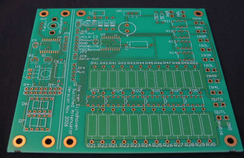
The circuit provides both audio volume and input channel selection. A stepwise volume control is implemented with a set of small relays and resistors. In a high-end audio system, a noticable sound improvement over potentiomeneters can be obtained, also over 'audio grade' potentiometers. Clearly, the IR remote control provides convenience over solutions with stepped attenuator rotary switches. The sealed relays will maintain contact quality over a practically endless lifetime.
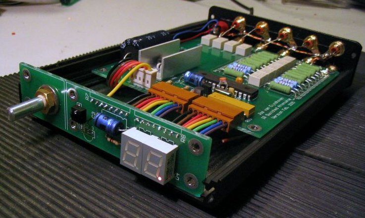
This page shows my audio volume control circuit and implementation. The circuit provides both audio volume and input channel selection. A stepwise volume control is implemented with a set of tiny relays and resistors. In a high-end audio system, a noticable sound improvement over potentiomeneters is obtained, also compared to 'audio grade' potentiometers. Its IR remote control provides convenience over solutions with stepped attenuator rotary switches. The sealed relays will maintain contact quality over a practically endless lifetime. The design represents a audio 'preamplifier' of top-class sonic quality, in a compact and affordable implementation. However, its passive nature results in a quite high output resistance, which limits general applicability.
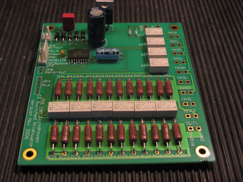
The design uses high-quality relays, and provides PCB space for somewhat larger audio-grade resistors. Normally I will provide RN60D mil-class resistors manufactured by Vishay-Dale, which have an excellent reputation for audio. In some tests by me, these indeed perform better than other good-quality industry-standard resistors. Of course you are free to apply more costly 'audiophile' resistors: I will be happy to learn about such results. The circuit targets high-end audio applications, particularly including tube-amplifier enthousiasts who prefer to avoid semiconductors in their signal path. However, very good sonic results have also been obtained with driving modern class-D amplifier modules.
This website provides schematics and documention, targetting DIY audio enthousiasts. This reflects my own involvement in 'audio' as hobbyist, although I attempt to create professional-quality things. Others are hopefully inspired, and create their own solutions, which I will happily learn about. To share my results, I also provide this design in limited quantities as a DIY building kit, see below. However, I do not freely distribute the firmware that is embedded in the microcontrollers: that gives some protection to my design, to support others who are interested in making a commercial derivative.
This attenuator design has the following features/characteristics:
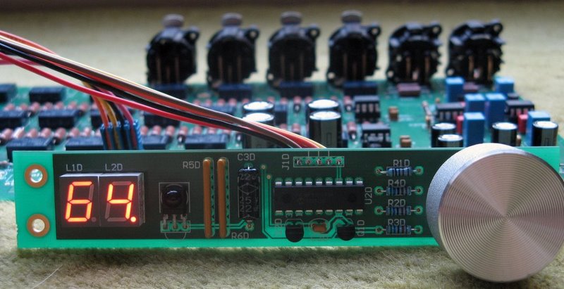
Compact and simple circuit: just 6 tiny relays implement a 64-step logarithmic stereo attenuator. The 64 steps of 1.0dB together span a 63dB audio attenuation range. By avoiding any active electronics, a very clean and open sound is maintained.
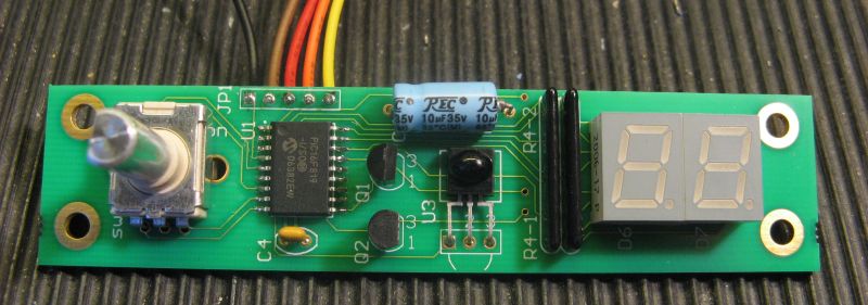
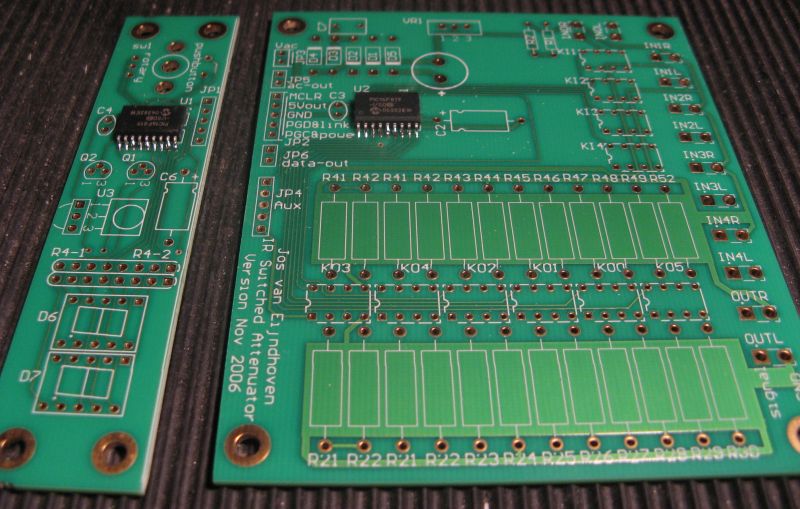
An IR receiver allows remote control. The IR 'eye' and a numeric display are on a small front-mount printed circuit board, separate from the relay board. The device can learn and store your favorite key codes. The controller understands the popular Philips 'RC5' protocol, Philips' newer 'RC6' protocol, and Sony's SIRC protocol. This also ensures interoperability with all 'generic' IR-controllers.
The PCB supports audio input channel selection: Four relays on the PCB allow selection between four audio input channels. If you really require more, you can add up to 3 extra input relays outside the PCB, to reach 7 input channels.
The PCB provides a 'power on/off' output signal, to drive an external power relay. This can be used to switch other equipment such as a power-amplifier. In power-off mode, the IR receiver and control remain active with a stand-by power of a few milliwatt.
The front display PCB can drive more than one relay PCB. Extra relay PCBs allow a multi-channel input select and volume control, for 5.1 or 7.1 sound, or for stereo audio with balanced (XLR) connections.
The circuit operates from an AC powersupply voltage of 6.0 to 7.5 volts. For tube amplifier builders: a spare 6.3V transformer winding will work fine.
An optional rotary switch can be mounted on the front PCB for manual control.
The circuit tries to avoid clicks/glitches in the audio output signal while making volume steps, due to carefully switching relays 'off' before others 'on'. However, you can clearly hear the mechanical activity of the relays. If you don't like that, relays are not your solution.
Resistor-Switch Networks for Audio Volume Control
This page provides background information to construct controllable attenuators for electronic signals, in particular targetting audio volume control. Different circuits are shown with their pros and cons.
Alternatively, you might want to check out neighbouring web pages for:
The actually implemented circuit design and PCB
A program to analyse your own switched-attenuator circuit design of any topology.
A small calculator to derive resistor values for a 'logarithmig ladder' attenuator.
Introduction
The traditional potentiometer is implemented with an electrical contact that slides over a resistive layer. An example of a well-known audio-grade potmeter is the Alps Blue. I still use this one myself.
A high-end (good and costly) alternative is the rotary switch. This device consists of a series of discrete resistors and switches, of which always one switch is actually closed. Resistor-switch networks can offer advantages over the potentiometer such as:
Improved quality of the electrical contact, in comparison with the slider.
Improved consistancy between separate audio channels (stereo or multi-channel)
Less sensitive to dust and wear.
Good audio attenuator rotary switches are made for instance by DACT.
An impressive DIY rotary attenuator is here. It is special in using two decks of switches and two sets of resistors per channel.
Nice switches and resistors are available for instance at www.triodes.nl.
Of course there are integrated circuits that implement a similar functionality, and where the mechanical switches are replaced by MOSFETs. See for instance National and Cirrus. Clearly such devices allow nicely compact solutions. However, for truly high-end audio, I do not trust the sound quality of such devices due to the non-linear parasitic capacitances in such switches.
This page focusses on an alternative solution, using discrete resistors and relays as switches. While maintaining the advantages of the rotary switches, the relays offer improved options for remote control of the attenuation, and the solution becomes trivially extendible to handle multi-channel control. Furthermore, the use of small mass-produced relays promises great quality-for-money for DIY audio enthousiasts. This is an example of such a project. A nice design is dicussed in this diyAudio thread.
Circuit Examples and Properties
Below, different circuits are presented. To obtain concise drawings and a fair comparison, all circuits are constructed to provide (just) 16 volume levels, with steps of 1.5dB, and with an impedance level of about 100Kohm.
Remind that for audio volume control you want a logarithmic scale, that means that for every successive step the signal amplitude should be scaled by a constant factor, or in other words, every step scales the amplitude with a fixed number of dBs. Such scaling gives a human impression of 'linear' sound level steps. (Note that the relay network in above link does not adhere to this property, but constant-voltage steps are made instead.)
For characterization the following properties are shown:
The number of resistors.
The number of switches.
The maximum number of closed switches in the signal path that carry audio current.
The input and output impedance curves for varying volume.
You might believe that, depending upon relay quality, the audio signal quality can degrade when passing through multiple (closed) contacts. Open contacts normally have such high impedance (low capacitance) that they will not affect audio quality. Similarly, having many resistors (and solder joints) might affect quality. Of course, the number of restistors and switches has a cost implication.
Rotary switch circuit
This circuit is similar to what is implemented in rotary-switch attenuators, and is in impedance behavior similar to a potentiometer.
The circuit contains 16 resistors and 16 switches, exactly 1 switch is closed at any setting.
Note the constant input resistance and the variable output resistance.
A calculation tool to design your own rotary switch circuit is found at SDS labs.
If the circuit would be loaded with an extra resistor, the circuit input impedance would also vary with the volume.
Logarithmic Ladder
This circuit is similar to the 'R-2R' ladder networks as used in D-A conversion, but modified to make exponential voltage steps in stead of linear steps. The 16 settings are obtained by closing the switches according to a 4-bit binary counter, with the most significant bit controlling Q1. The first stage (around Q1) creates a constant output resistance of 25Kohm. This resistance is kept constant between every stage.
The circuit contains only 7 resistors and 4 switches, all 4 switches might simultaneously carry audio current.
Note the varying input resistance and the almost constant output resistance.
A calculation tool to design your own staged attenuator circuits like this one is on this page.
Intermediate circuit: at most 2 switches closed
Allow only two switches to simultaneously carry audio current, and reduce the number of components in comparison with the rotary switch circuit:
This circuit is designed to close exactly 1 switch of the first stage and one switch of the second stage. The first stage implements steps of -6dB, the second stage makes steps of -1.5 dB.
It counts 11 resistors and 8 switches, of which 2 can simultaneously carry audio current.
Note the 1.3 dB attenuation in the 'fully open' setting.
The Switch-Resistor Circuit Analysis Program
You can analyze your own circuit diagram, and generate the same kind of figures with the program provided on this separate page...
Implementation Hints...
For actual implementation you probably want more than 16 steps, reaching lower than -24 dB. The above circuits are not hard to extend, but on interest I could publish such schematics here.
Relays
For high-end audio application, you need good quality small-signal relays. Some older, larger, relays which I had lying around did not perform satisfactory. After going through datasheets, I bought a set of NAIS TQ2 relays. These small (DIP) relays behave nicely transparent. They are easily available at many sites for prices between $1.50 and $7 (for instance here). For a stereo 32-step 'logarithmic ladder' you would need only 5 of these.
(I assume that other quality small-signal relays will be fine as well, such as the OMRON G6K.)
Controller
To control the relays one can create hardwired logic. The more advanced hobbyist could use a microcontroller like a PIC 16F88 or 16F818. This allows an implementation with very few components, and direct attachment of an infra-red receiver for a remote control. Next to that, a simple (mono linear) potentiometer can be attached which operates on DC only, of which the DC slider voltage is read by the PIC A/D converter, to control the relays also manually. To buffer the PIC outputs to the relays, an additional IC like the ULN2003 is nice to have.
|
|
|
| |
Accurate LC Meter
Build your own Accurate LC Meter (Capacitance Inductance Meter) and start making your own coils and inductors. This LC Meter allows to measure incredibly small inductances making it perfect tool for making all types of RF coils and inductors. LC Meter can measure inductances starting from 10nH - 1000nH, 1uH - 1000uH, 1mH - 100mH and capacitances from 0.1pF up to 900nF. The circuit includes an auto ranging as well as reset switch and produces very accurate and stable readings. |
|
PIC Volt Ampere Meter
Volt Ampere Meter measures voltage of 0-70V or 0-500V with 100mV resolution and current consumption 0-10A or more with 10mA resolution. The meter is a perfect addition to any power supply, battery chargers and other electronic projects where voltage and current must be monitored. The meter uses PIC16F876A microcontroller with 16x2 backlighted LCD. |
|
|
|
60MHz Frequency Meter / Counter
Frequency Meter / Counter measures frequency from 10Hz to 60MHz with 10Hz resolution. It is a very useful bench test equipment for testing and finding out the frequency of various devices with unknown frequency such as oscillators, radio receivers, transmitters, function generators, crystals, etc. |
|
1Hz - 2MHz XR2206 Function Generator
1Hz - 2MHz XR2206 Function Generator produces high quality sine, square and triangle waveforms of high-stability and accuracy. The output waveforms can be both amplitude and frequency modulated. Output of 1Hz - 2MHz XR2206 Function Generator can be connected directly to 60MHz Counter for setting precise frequency output. |
|
|
|
BA1404 HI-FI Stereo FM Transmitter
Be "On Air" with your own radio station! BA1404 HI-FI Stereo FM Transmitter broadcasts high quality stereo signal in 88MHz - 108MHz FM band. It can be connected to any type of stereo audio source such as iPod, Computer, Laptop, CD Player, Walkman, Television, Satellite Receiver, Tape Deck or other stereo system to transmit stereo sound with excellent clarity throughout your home, office, yard or camp ground. |
|
USB IO Board
USB IO Board is a tiny spectacular little development board / parallel port replacement featuring PIC18F2455/PIC18F2550 microcontroller. USB IO Board is compatible with Windows / Mac OSX / Linux computers. When attached to Windows IO board will show up as RS232 COM port. You can control 16 individual microcontroller I/O pins by sending simple serial commands. USB IO Board is self-powered by USB port and can provide up to 500mA for electronic projects. USB IO Board is breadboard compatible. |
|
|
|
|
ESR Meter / Capacitance / Inductance / Transistor Tester Kit
ESR Meter kit is an amazing multimeter that measures ESR values, capacitance (100pF - 20,000uF), inductance, resistance (0.1 Ohm - 20 MOhm), tests many different types of transistors such as NPN, PNP, FETs, MOSFETs, Thyristors, SCRs, Triacs and many types of diodes. It also analyzes transistor's characteristics such as voltage and gain. It is an irreplaceable tool for troubleshooting and repairing electronic equipment by determining performance and health of electrolytic capacitors. Unlike other ESR Meters that only measure ESR value this one measures capacitor's ESR value as well as its capacitance all at the same time. |
|
Audiophile Headphone Amplifier Kit
Audiophile headphone amplifier kit includes high quality audio grade components such as Burr Brown OPA2134 opamp, ALPS volume control potentiometer, Ti TLE2426 rail splitter, Ultra-Low ESR 220uF/25V Panasonic FM filtering capacitors, High quality WIMA input and decoupling capacitors and Vishay Dale resistors. 8-DIP machined IC socket allows to swap OPA2134 with many other dual opamp chips such as OPA2132, OPA2227, OPA2228, dual OPA132, OPA627, etc. Headphone amplifier is small enough to fit in Altoids tin box, and thanks to low power consumption may be supplied from a single 9V battery. |
|
|
|
|
|
Arduino Prototype Kit
Arduino Prototype is a spectacular development board fully compatible with Arduino Pro. It's breadboard compatible so it can be plugged into a breadboard for quick prototyping, and it has VCC & GND power pins available on both sides of PCB. It's small, power efficient, yet customizable through onboard 2 x 7 perfboard that can be used for connecting various sensors and connectors. Arduino Prototype uses all standard through-hole components for easy construction, two of which are hidden underneath IC socket. Board features 28-PIN DIP IC socket, user replaceable ATmega328 microcontroller flashed with Arduino bootloader, 16MHz crystal resonator and a reset switch. It has 14 digital input/output pins (0-13) of which 6 can be used as PWM outputs and 6 analog inputs (A0-A5). Arduino sketches are uploaded through any USB-Serial adapter connected to 6-PIN ICSP female header. Board is supplied by 2-5V voltage and may be powered by a battery such as Lithium Ion cell, two AA cells, external power supply or USB power adapter. |
|
200m 4-Channel 433MHz Wireless RF Remote Control
Having the ability to control various appliances inside or outside of your house wirelessly is a huge convenience, and can make your life much easier and fun. RF remote control provides long range of up to 200m / 650ft and can find many uses for controlling different devices, and it works even through the walls. You can control lights, fans, AC system, computer, printer, amplifier, robots, garage door, security systems, motor-driven curtains, motorized window blinds, door locks, sprinklers, motorized projection screens and anything else you can think of. |
|
|
|