The TX has a built-in "mini-mixer" which makes it possible to use it without any external mixing table. This consists of the transistor T1, which amplify the mike signal before it gets combined with the CD (or tape) one. R1 and 2 are adjustable resistors (potentiometers) which are used to set the audio level (see the tuning section).
The component between R8 and C21 is the oscillator, the part which generates the radio signal. The diode D1 is a so-called "varicap", which can be seen as an variable capacitor, controlled by the audio signal. That, C12, 13, and the coil L1 decides the frequency. The oscillator is actually two oscillators, operating in antiphase around 50MHz. When the two signals are combined, they make a 100MHz signal. This setup is generally much more stable than one oscillator operating directly at 100MHz. The signal is then amplified up to 1W in T4.
To the far right is a the tuning aid, which rectifies a part of the output and controls the LED D5. The higher output, the brighter is D5.
Parts list
Resistors:

R1+2          10k pot

R3            820k

R4            4.7k

R5-7+19       220r

R8            1.5k

R9            15k

R10+11        1k

R12           33k

R13+14        56r

R15+16        68k

R17           47r

R18           270r

R20           10k


Capacitors:

If nothing else is stated, use ceramic or mica types.

C1, 2, 7, 16, 17, 19,

24, 29 & 31   1n

C3-5 & 8      10u elect.

C6, 18 & 30   220u elect.

C9, 10 & 20   10n

C11           27p*

C12           47p*

C13           30p trimmer

C14 & 15      15p*

C21, C25 & 26 65p trimmer

C22           100p

C23           5.6p

C27 & 28      1.8p

*C11, 12, 14 and 15 affects the frequency, for best results use high-quality capacitors.

(Kerko-500 ...)


Coils:

Free-standing air-core types, wound of 1mm cu wire.

Wind closely on a pin or similar with the right diameter,

then carefully pull them out to the right length. Make sure the ends are as in fig. 2.


Fig. 2: Proper winding


L1    6 coils, each of 2 turns, 5mm internal dia and 5mm length

L2    3 turns, 7mm dia and 7mm length

L3    4 turns, 5mm dia and 7mm length

L4    6 turns, 5mm dia and 10mm length


RF choke (H1):

This can be made of a resistor of 33k, which you wind app 1/2m of 0.2mm enameled wire around,

and solder to each end.


Diodes:

D1 is a "dual varicap" (with facing cathodes) selected for the absolutely best

sound quality. It's not critical, almost any varicap(s) will do. In a pinch, even some

regular RF diodes might work (you might have to increase the value of C11 a bit).

D1       KV1310 or two MV209

D2+3     1N4148

D4       1N4001

D5       Standard LED


Transistors:

T1+5     BC548 or BC549

T2+3     BF494 or BF199

T4       2N4427 or 2N3866


Fig. 3: Pin positions of transistors and regulator, seen from below


I1 is a standard 5 volts stabilizer, which gives a constant voltage to D1,

even if the supply varies. This keeps the TX better on frequency.

I1:     78L05


Misc:

Enclosure

BNC socket

2 X 3.5mm jack sockets

Power supply socket

Power supply

Antenna

Mike

CD/tape player
Assembly
Fig 4: PCB layout for the 1W Veronica
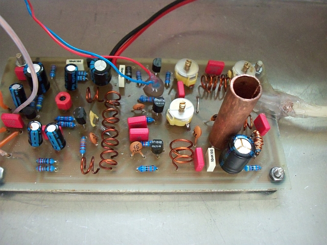
The transmitter is to be built on the PCB in fig. 4. RF stuff is pretty sensitive to poor PCB layout, avoid using veroboard or similar.
The components should be placed as flat as possible on the board, with short wires. The transmitter should be mounted in a shielded metal enclosure (connected to circuit ground), like these die-cast aluminum "block" enclosures. Use 3mm bolts with 5-10mm spacers, to create a good electrical connection.
The transistor T4 needs a little heatsink to cool it off. This could be made from a 2cm long piece of metal pipe, with slightly smaller diameter than the transistor. Cut a length ways slot in the pipe, so it can be bent a bit out, and put on. Make some holes in the lid above it, to ensure air circulation. The heatsink is connected directly to the collector of T4, so make sure it doesn't get too close to the lid (app 5mm distance). The mike and CD connections could be done with 3.5mm jack plugs, while the power could be done with such a plug that's often used with power supplies. For the antenna output I would recommend BNC plugs (like those used with some computer networks). The sockets' ground side should have a good connection to the enclosure, and internal wire should be made as short as possible (especially important with the antenna connection!). It's wise to mount D5 in the lid, so you constantly can see if the transmitter is operating properly.
Fig 5: Component placement
Power supply
The transmitter is to be powered by 9 to 16 volts DC, with 16V it'll give 1W, 12V gives 600mW, while 9V will give just 200mW. Use a good quality power supply, or else you might risk that the frequency changes or "hum" in the audio.
If you intend to power the transmitter with batteries or a poor supply, you should add an extra voltage stabilizer (shown at the top of fig. 1), instead of D1 (place with backside towards PCB edge). This is of the 78XX type, where XX is it's output voltage (for instance 7815 for 15V). Remember that the input voltage needs to be at least 2.5V higher for the stabilizer to work properly. The capacitor is 10n.
Antennas
It's important that the antenna and cable has the same impedance, and that this suits the transmitter. If not, you'll get a "mismatch", which means that you transmit with lower power and in worst case can burn out the transistor. This impedance is normally 50 or 75 ohms.
The most common antenna is the dipole, shown in fig. 6A. It could be made with thick wire (or welding rods), which is mounted with BNC plugs. The length of these (in meters) is about 70/f, where f is the operating frequency in MHz. If you're not sure which frequency you're gonna use, make them 70cm (28"). B shows how the BNC plugs should be put together. The upper element should only be connected to the center pin of the plug, while the lower one should be connected to the shield.
For best performance, this antenna should have a "balun" to give both the elements the same impedance to ground. This is easiest done by making 4-5 turns (app. 20cm /8") on the cable. The antenna should be mounted vertically, and the cable should preferably be lead town at least 50cm (20") from the lower element.
Fig 6: Dipole and GP antenna
Another suitable antenna is the so-called "Quarter wave Ground plane", as shown in fig. 6C. It consists of 5 elements of the same type and length as on the dipole. The center one radiates the signal, while the others make a so-called ground plane. D shows how the elements are assembled with a chassis-mount BNC socket. The middle rod is soldered to the center connector, while the lower ones are soldered in the bolt holes. They could preferable be bent under (an soldered to) the next as shown, to give mechanical strength. These rods should not point straight out, but be bent 30-45 degrees downwards. This antenna has 50 ohms impedance, and should be connected to a 50 ohms cable
without a balun. It's important that the antenna is placed high and free. At FM frequencies, the transmitting power don't affect the range much, it's more important to have a clear view towards the listeners. If you put a little effort in finding a good location, you can get quite far even with a small transmitter. The antenna should be placed outdoors (preferably on the roof) since both trees and buildings obstruct FM signals. If someone starts asking, remember that such an antenna is good for reception too!
Tuning
In order to make the transmitter operate properly, it needs to be tuned. To this I'll recommend you to make a so-called dummy-load, which makes it easier to distinguish the main signal from weaker ones. This is a resistor of 47 or 68 ohms (corresponding to the antenna you intend to use), which is soldered to an antenna plug. Make sure the resistors can handle the power from the transmitter, and that they're not wire-wound. Don't
ever turn on a transmitter without antenna or dummy, or else the output stage might blow.
Set all the trimmer capacitors to middle position (the upper plates cover half the lower ones), connect the dummy to the antenna output and a CD player to the CD input. When you switch on, the LED should light a bit (if not, try adjusting C21) and the transmitter operate around 98MHz. Use a small screwdriver with insulated handle (to not affect the circuit) and tune C21, 25 and 26 for maximum LED brightness. Then adjust C13 carefully up or down (depends on which frequency you intend to use) until the LED dims, but not goes completely out. Then tune the other trimmers until the LED is bright again. Continue this way until you get the frequency where you want it. Check with a radio to ensure that you're only transmitting on a single place in the band, if not you might have to re-tune from the beginning. If you have trouble reaching the ends of the band, L1 must be changed a bit.
Carefully squeeze the turns a bit closer together to go down in frequency, increase the spacing to go up. Make sure these six coils are as identical as possible - if they're very different the transmitter may put out an unclean signal.
Now adjust R2 until the CD player sound as loud as the other stations. Be ware that many stations uses "compression" in order to make the sound seem louder than it actually is, and if you set it that loud, you might over-modulate. This might cause noise in neighbor channels, and must be avoided at all times. Similarly you must be careful not to set the mike (or talk) too loud, the best is to have an external mixer with some kinda ALC (automatic level control).
Don't get pissed if it doesn't work at first, transmitters generally requires a bit of fiddling and patience...
The 5W version
The 5W version of the Veronica is pretty similar to the 1W one, but with an extra amplifier stage (T6). As mentioned, the MRF 237 transistor costs around $20, and should be handled accordingly.
Fig 7: The output stage of Veronica 5W. Everything to the left of T4 is identical to the 1W one.
Parts list
Parts not mentioned are identical to the 1W version.
R19       10r

R20       22r

R21       1.5k

R22       270r


C23       15p

C24       33p

C28       5.6p

C32 & 34  47p

C33       22p

C35 & 38  1n

C36       220n

C37       100p


L3   3 turns, 6mm dia and 8mm long

L4   Made of an ordinary 2.2k resistor (app 2mm dia) on which you make 14 turns of

0.2 mm enameled wire, and solder to each side. In addition it should have a ferrite

bead (of the same type as the RF chokes) on each pin.

L5   5 turns, 6mm dia and 11mm long

L6   4 turns, 6mm dia and  9mm long


Fig 8: L4, pin position of T6 and dummy-load


The RF chokes should be made of enameled wire on ferrite beads (app 5mm long, 4mm dia).

Make sure you get beads suited for frequencies around 100MHz, so-called "material 43"

should do the trick. The wire is wound through the hole, so that

through-around-and-through-again is one turn. If you can't get hold of such beads,

you could make the chokes as in the 1W version.

H1    5 turns

H2    1 turn

H3    2 turns

H4    3 turns

T6    MRF237
I got a letter from Dragan Stojanovic, where he told that he'd used a 2N3926, which I guess it's cheaper and easier to get hold of then the MRF237. But note that if that one is like most RF transistors, the collector is connected to the casing. You may have to redesign the heatsink a bit, so it's
insulated (important!) from ground, and won't create too much capacitance.
Assembly
Fig 9: PCB for Veronica 5W
The output transistor T6 needs a heatsink. This is made from an L-shaped aluminum profile, app 14cm long, 2.5cm side width and 3mm material thickness (see fig. 10). The hole for T6 must be made as accurate as possible (measure the transistor itself for exact dia). If you make a slot as shown, you could carefully bend the heatsink out a bit to get the transistor in. Use silicone grease if you have it! The heatsink is mounted with 4 screws to the PCB (the two outermost also to fix it in the enclosure). You probably need to use one or two washers between PCB and heatsink, due to the edge of T6. If you're using a dia-cast aluminum enclosure, you should bolt the heatsink to the inside of this, use silicone grease here, too. It might be some hassle to get the pins of T6 to fit in the holes in the PCB (solder in place after assembling the heatsink), The easiest way is to drill the holes a bit too large (2mm), and bend the pins down to the PCB surface. T4 should have the same type of cooling cap as in the 1W version.
The antenna output is made so that the antenna plug can be mounted right on the PCB. This is not very practical when the transmitter is mounted in the box, but it can be useful during testing.
Fig 10: PCB placement of the Veronica 5W
This transmitter can be powered with 9-16V, 12V is the best (it draws app 900mA). If you have a voltage stabilizer, it should be placed instead of D4 like shown. It needs cooling, and should be bolted to the heatsink.
The Veronica 5W is tuned the same way as the 1W one, but you'll need a larger dummy. If you can't get a resistor that handles 5W (
not wire-wound!), you could make it as in fig 10, with three 2W resistors connected in parallel to an antenna plug. For a 50 ohm dummy the values should be 150 ohms, for a 75 ohm one 220 ohms.