| FM Transmitter Component List:
|
Resistors:
1M brown, black, green
47K yellow, violet, orange
22K red, red, orange
10K brown, black, orange
470R yellow, violet, brown
Capacitors:
1n ceramic 102
5p6 ceramic
22n ceramic 223
27p ceramic
100n monoblock
Transistors:
BC547
Air Coil
Trimcap
Electret microphone
Aerial wire 165cm |
|
|
|
|
| FM Transmitter Technical
Specifications:
|
Power: Requires 2 AA batteries, 9 volt battery can be used to increase range
Voltage Supply: 88-108MHz
Transmitter Distance: 300m or more
Dimensions: 1-3/4" (L) 3/4" (W) 1/2" (H)
FM Transmitter frequency is user selectable
Transmitter can be listened to on any FM radio
|
|
|
|
FM Transmitter
| |
This FM transmitter is about the simplest and
most basic FM transmitter it is possible to build and have a useful
transmitting range. It is surprisingly powerful despite its
small component count and 3V operating voltage. It will
easily transmit over 300 meters in the open air and even more with higher voltage supply.
The circuit we use is based on a proven Australian design.
It may be tuned anywhere in the FM band. Or it may be
tuned outside the commercial M band for greater privacy.
Of course this means you must modify your FM radio to
be able to receive the transmission or have a broad-band
FM receiver.
The output power of FM transmitter is within the legal limits
of many countries. However,
some countries may ban all wireless FM transmitters
without a licence. It is your responsibility
to check the legal requirements for the operation
and to obey them.
FM transmitter is constructed on a single-sided printed circuit
board PCB.
|
FM Transmitter Instructions
| |
Components may be added to the PCB in any order. Note
that the electret microphone should be inserted with the
pin connected to the metal case connected to the negative
rail (that is, to the ground or zero voltage side of the
circuit). The coil should be about 3mm in diameter and 5
turns. The wire is tinned copper wire, 0.61 mm in diameter.
After the coil in soldered into place spread the coils apart
about 0.5 to 1mm so that they are not touching. (The
spacing in not critical since tuning of FM transmitter will be done
by the trim capacitor. It is quite possible, but not as
convenient, to use a fixed value capacitor in place of the
trimcapacitor - say 47pF - and to vary the Tx frequency by
simply adjusting the spacing of the coils. That is by
varying L of the LC circuit rather than C.) Adding and
removing the batteries acts as a switch.
Connect a half or quarter wavelength antenna (length of
wire) to the aerial point. At an FM frequency of 100 MHz
these lengths are 150 cm and 75 cm respectively.
|
FM Transmitter Circuit Description
| |
This FM transmitter is about the simplest and most basic FM transmitter it is possible to build and have a useful transmitting range. It is surprisingly powerful despite its small component count and 3V operating voltage. It will easily transmit over 300 meters in the open air and even more with higher voltage supply. The circuit we use is based on a proven Australian design. It may be tuned anywhere in the FM band. Or it may be tuned outside the commercial M band for greater privacy. Of course this means you must modify your FM radio to be able to receive the transmission or have a broad-band FM receiver. The output power of FM transmitter is within the legal limits of many countries. However, some countries may ban ALL wireless FM transmitters without a licence. It is your responsibility to check the legal requirements for the operation and to obey them. FM transmitter is constructed on a single-sided printed circuit board PCB.
|
FM Transmitter Circuit Description
| |
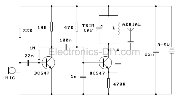
The circuit is basically a radio frequency (RF) oscillator
that operates around 100 MHz. Audio picked up and
amplified by the electret microphone is fed into the audio
amplifier stage built around the first transistor. Output
from the collector is fed into the base of the second
transistor where it modulates the resonant frequency of
the tank circuit (the 5 turn coil and the trimcap) by varying
the junction capacitance of the transistor. Junction
capacitance is a function of the potential difference
applied to the base of the transistor. The tank circuit is
connected in a Colpitts oscillatorcircuit. Let us look at the individual blocks of the circuit
more closely:
The electret microphone: an electret is a permanently
charged dielectric. It is made by heating a ceramic material,
placing it in a magnetic field then allowing it to cool while
still in the magnetic field. It is the electrostatic equivalent
of a permanent magnet. In the electret microphone a slice
of this material is used as part of the dielectric of a
capacitor in which the diaphram of the microphone forms
one plate. Sound pressure moves one of its plates. The
movement of the plate changes the capacitance. The
electret capacitor is connected to an FET amplifier. These
microphones are small, have excellent sensitivity, a wide
frequency response and a very low cost.
First amplification stage: this is a standard self-biasing
common emitter amplifier. The 22nF capacitor isolates the
microphone from the base voltage of the transistor and
only allows alternating current (AC) signals to pass.
The tank (LC) circuit: every Tx needs an oscillator to
generate the radio Frequency (RF) carrier waves. The tank
(LC) circuit, the BC547 and the feedback 5pF capacitor are
the oscillator in the Cadre. An input signal is not needed
to sustain the oscillation. The feedback signal makes the
base-emitter current of the transistor vary at the resonant
frequency. This causes the emitter-collector
current to vary at the same frequency. This signal fed to
the aerial and radiated as radio waves. The 27pF coupling
capacitor on the aerial is to minimise the effect of the aerial
capacitance on the LC circuit.
The name 'tank' circuit comes from the ability of the LC
circuit to store energy for oscillations. In a pure LC circuit
(one with no resistance) energy cannot be lost. (In an AC
network only the resistive elements will dissipate electrical
energy. The purely reactive elements, the C and the L
simply store energy to be returned to the system later.)
Note that the tank circuit does not oscillate just by having
a DC potential put across it. Positive feedback must be
provided. (Look up Hartley and Colpitts oscillators in a
reference book for more details.) |
FM Transmitter Circuit Calibration
| |
Place the transmitter about 10 feet from a FM radio. Set
the radio to somewhere about 89 - 90 MHz. Walk back to
the FM transmitter and turn it on. Spread the winding of the coil
apart by approximately 1mm from each other. No coil
winding should be touching another winding. Use a small
screw driver to tune the trim cap. Remove the screwdriver
from the trim screw after every adjustment so the LC
circuit is not affected by stray capicitance. Or use a plastic
screwdriver. If you have difficulty finding the transmitting
frequency then have a second person tune up and down
the FM dial after every adjustment.
One full turn of the trim cap will cover its full range of
capacitance from 6pF to 45pF. The normal FM band tunes in over about one tenth of the full range of the tuning cap.
So it is best to adjust it in steps of 5 to 10 degrees at each
turn. So tuning takes a little patience but is not difficult.
The reason that there must be at least 10 ft. separation
between the radio and FM transmitter is that the FM transmitter emits
harmonics; it does not only emit on one frequency but on
several different frequencies close to each other.
You should have little difficulty in finding the FM transmitter
frequency when you follow this procedure.
|
What if FM Transmitter Desn't Work
| |
Poor soldering is the most likely reason that the circuit
does not work. Check all solder joints carefully under a
good light. Next check that all components are in their
correct position on the PCB. Thirdly, follow the track with
a voltmeter to check the potential differences at various
parts of the circuit particularly across the base, collector
and emitter of the two transistors.
Are the transistors in the correct way. Is the battery flat.
Check the collector-emitter voltages (1.0 to 1.5 V). This
will tell you that the battery potential difference is across
those components.
It is possible that due to variations in tolerance the 22K
load resistor of the microphone may have to be increased
or decreased to get the best response. Reducing the value
will increase the sensitivity.
|
What to Learn from Building FM Transmitter
| |
It should already be clear from the above circuit
description that there is a surprising amount of electronics
which may be learnt from this deceptively simple kit. Here
is a list of some advanced topics in electronics which can
be demonstrated or have their beginnings in this kit: Class
C amplifiers; FM transmission; VHF antennas; positive
and negative feedback; stray capacitance; crystal-locked
oscillators; signal attenuation
The simple halfwave antennae used in the kit is not the
most efficient. Greater efficiency may be gained by
connecting a dipole antennae using 50 ohm coaxial cable.
Connect one lead to the Anrenna point and the other to
the earth line.
You may experiment with using 6V or 9V with the circuit to
see how this increases the range of the transmitter. The
sensitivity may be increased by lowering the 22K resistor
to 10K. Try it and see.
Note that this FM transmitter is not suitable for use on your body, for
example, in your pocket. This is because it is affected by
external capacitance and the transmitting frequency drifts
depending how close you are to it. Stray capacitance is
automatically incorporated into the capacitance of the tank
circuit which will shift the transmitting frequency.
|
FM Transmitter Kit
| |
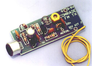
You can purchase a complete FM Transmitter kit at Electronics-DIY
store. Please see the link for more details.
|
Related Links
|
|
|
| |
Accurate LC Meter
Build your own Accurate LC Meter (Capacitance Inductance Meter) and start making your own coils and inductors. This LC Meter allows to measure incredibly small inductances making it perfect tool for making all types of RF coils and inductors. LC Meter can measure inductances starting from 10nH - 1000nH, 1uH - 1000uH, 1mH - 100mH and capacitances from 0.1pF up to 900nF. The circuit includes an auto ranging as well as reset switch and produces very accurate and stable readings. |
|
PIC Volt Ampere Meter
Volt Ampere Meter measures voltage of 0-70V or 0-500V with 100mV resolution and current consumption 0-10A or more with 10mA resolution. The meter is a perfect addition to any power supply, battery chargers and other electronic projects where voltage and current must be monitored. The meter uses PIC16F876A microcontroller with 16x2 backlighted LCD. |
|
|
|
60MHz Frequency Meter / Counter
Frequency Meter / Counter measures frequency from 10Hz to 60MHz with 10Hz resolution. It is a very useful bench test equipment for testing and finding out the frequency of various devices with unknown frequency such as oscillators, radio receivers, transmitters, function generators, crystals, etc. |
|
1Hz - 2MHz XR2206 Function Generator
1Hz - 2MHz XR2206 Function Generator produces high quality sine, square and triangle waveforms of high-stability and accuracy. The output waveforms can be both amplitude and frequency modulated. Output of 1Hz - 2MHz XR2206 Function Generator can be connected directly to 60MHz Counter for setting precise frequency output. |
|
|
|
BA1404 HI-FI Stereo FM Transmitter
Be "On Air" with your own radio station! BA1404 HI-FI Stereo FM Transmitter broadcasts high quality stereo signal in 88MHz - 108MHz FM band. It can be connected to any type of stereo audio source such as iPod, Computer, Laptop, CD Player, Walkman, Television, Satellite Receiver, Tape Deck or other stereo system to transmit stereo sound with excellent clarity throughout your home, office, yard or camp ground. |
|
USB IO Board
USB IO Board is a tiny spectacular little development board / parallel port replacement featuring PIC18F2455/PIC18F2550 microcontroller. USB IO Board is compatible with Windows / Mac OSX / Linux computers. When attached to Windows IO board will show up as RS232 COM port. You can control 16 individual microcontroller I/O pins by sending simple serial commands. USB IO Board is self-powered by USB port and can provide up to 500mA for electronic projects. USB IO Board is breadboard compatible. |
|
|
|
|
ESR Meter / Capacitance / Inductance / Transistor Tester Kit
ESR Meter kit is an amazing multimeter that measures ESR values, capacitance (100pF - 20,000uF), inductance, resistance (0.1 Ohm - 20 MOhm), tests many different types of transistors such as NPN, PNP, FETs, MOSFETs, Thyristors, SCRs, Triacs and many types of diodes. It also analyzes transistor's characteristics such as voltage and gain. It is an irreplaceable tool for troubleshooting and repairing electronic equipment by determining performance and health of electrolytic capacitors. Unlike other ESR Meters that only measure ESR value this one measures capacitor's ESR value as well as its capacitance all at the same time. |
|
Audiophile Headphone Amplifier Kit
Audiophile headphone amplifier kit includes high quality audio grade components such as Burr Brown OPA2134 opamp, ALPS volume control potentiometer, Ti TLE2426 rail splitter, Ultra-Low ESR 220uF/25V Panasonic FM filtering capacitors, High quality WIMA input and decoupling capacitors and Vishay Dale resistors. 8-DIP machined IC socket allows to swap OPA2134 with many other dual opamp chips such as OPA2132, OPA2227, OPA2228, dual OPA132, OPA627, etc. Headphone amplifier is small enough to fit in Altoids tin box, and thanks to low power consumption may be supplied from a single 9V battery. |
|
|
|
|
|
Arduino Prototype Kit
Arduino Prototype is a spectacular development board fully compatible with Arduino Pro. It's breadboard compatible so it can be plugged into a breadboard for quick prototyping, and it has VCC & GND power pins available on both sides of PCB. It's small, power efficient, yet customizable through onboard 2 x 7 perfboard that can be used for connecting various sensors and connectors. Arduino Prototype uses all standard through-hole components for easy construction, two of which are hidden underneath IC socket. Board features 28-PIN DIP IC socket, user replaceable ATmega328 microcontroller flashed with Arduino bootloader, 16MHz crystal resonator and a reset switch. It has 14 digital input/output pins (0-13) of which 6 can be used as PWM outputs and 6 analog inputs (A0-A5). Arduino sketches are uploaded through any USB-Serial adapter connected to 6-PIN ICSP female header. Board is supplied by 2-5V voltage and may be powered by a battery such as Lithium Ion cell, two AA cells, external power supply or USB power adapter. |
|
200m 4-Channel 433MHz Wireless RF Remote Control
Having the ability to control various appliances inside or outside of your house wirelessly is a huge convenience, and can make your life much easier and fun. RF remote control provides long range of up to 200m / 650ft and can find many uses for controlling different devices, and it works even through the walls. You can control lights, fans, AC system, computer, printer, amplifier, robots, garage door, security systems, motor-driven curtains, motorized window blinds, door locks, sprinklers, motorized projection screens and anything else you can think of. |
|
|
|
|
|


