| 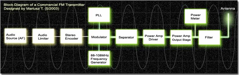
The above picture shows the basic stages of the commercial
transmitter, its blocks/stages and how they are connected
with each other. I would like to describe each of these
block independently so it could help the beginners see
the big picture and thus better understand how transmitters
are designed. So lets start!
Audio Source
| |
Also
referred to as Audio Frequency (AF) which usually
is around 20Hz-20KHz. This can be either CD player,
computer, tape, microphone or just about any other
audio device. The audio signal should have as good
characteristics and quality as possible. Connectors
from Audio Source to the Audio Limiter should also
be of a better quality to make sure that there isn't
any noise coming to the audio stages of a transmitter
(yellow blocks). |
Audio Limiter
| |
Also
known as Compressor or Automatic Level Control.
This circuit is usually built using operational
amplifiers in conjunction with other controlling
IC's. And these are the following task of this device:
1.
Provides 100% of allowable modulation. In other
words the level of incoming sound is a maximum that
modulator can handle (perfectly matched with the
sensitivity of the modulator). That's why the sound
on the receiver is very high but at the same time
very clear.
2. Prevents over modulation. The best thing is to
keep modulation to the maximum (100%) but if that
allowable line is crossed then there would be over
modulation of audio cycle when the RF carrier is
removed completely from the air thus producing distortion
in the transmission. How does that happen? In most
of the transmitters the same block or even a transistor
is responsible for both modulation and generation
of the carrier frequency (88-108MHz). If over modulation
takes place transistor (Q1) becomes so unstable
that it cannot generate a clear carrier frequency
and in result we hear the distortion.
3. Keeps an audio on the same level. This is especially
crucial when using microphone as a source because
its dynamics (audio levels) are never steady. When
playing music, some of the tracks might be recorded
at different audio levels and when a user receives
a given radio station he or she doesn't want to
set an audio level every few minutes or so, you
want the sound loudness to always be the same.
If you just want to build a simple transmitter so
you can transmit your music around the house you
can live without automatic level control but then
you'll need to make sure that audio signal of your
source is set to minimum level and that it is matched
with your transmitter.
|
Stereo Encoder
| |
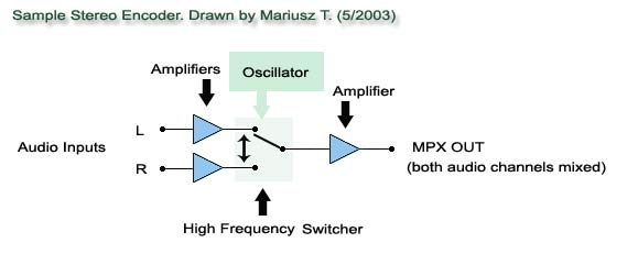
Also known as encoder, coder or multiplexer (MPX). Stereo encoder
is a circuit that takes both channels of audio (L and R)
and mixes it into one so called MPX channel.
Stereo encoder uses a process called multiplexing which allows to transmit more than one signal over a single link, route, or a channel. The circuit is driven by an oscillator that switches between the two channels of audio
with a frequency of 38KHz per second to merge these
channels into one. Additionally, 38KHz frequency is divided in half to produce a 19KHz PILOT tone that receiver will need to use to decode MPX signal back into two audio channels. Once the two audio channels are mixed and 19KHz frequency is generated they are then merged together to form a MPX signal that FM transmitter will transmit. |
Modulator
| |
This
block places audio frequency on top of a carrier
frequency (frequency in which one wants to transmit,
in our case 88-108MHz). We may also refer to this
block as a mixer because it mixes two different frequencies. |
Oscillator
| |
Just as the name implies oscillator oscillates or generates a carrier
frequency (88-108MHz). Oscillator can generate various types of
frequencies and may be used for many different purposes.
It can be found in most of the electronic devices
and in our case it is found in all FM transmitters
and receivers as well. A simple one transistor FM
transmitter is in fact nothing else but an oscillator
and a modulator. An output power of one transistor
oscillators found in these transmitters is often very
small, 50mW or below. If such transmitter does not
have at least a separator or an amplifier then in
that case this oscillator is very prone to frequency
drifts. A single touch to its antenna may cause a
slight frequency change.
Oscillator Types:
1. VFO (Variable Frequency Oscillator) -
An oscillator whose output frequency can be changed by adjusting a variable inductor or variable capacitor.
2. VCO (Voltage Controlled Oscillator) - An oscillator whose output frequency is controlled or changed by an application of external voltage. VCO uses varicap diode that changes the capacitance as different levels of voltage are applied.
3. PLL (Phase Locked Loop) -
A circuit that synchronizes a frequency of VCO with a frequency of a reference oscillator by using a comparison of phase between the two signals.
PLL takes a frequency of VCO, divides it into a lower frequency which can be compared with a stable reference oscillator. Then amplifiers are used to send an appropriate voltage back to the VCO to keep the desired frequency stable.
4. Crystal Oscillator - Oscillator that uses a crystal to generate a frequency.
|
Separator
| |
This
is usually a single transistor that separates a low
oscillator's signals from an antenna or the rest of
the blocks. When separator is in place it usually
brings a greater oscillator's stability especially
in low power transmitters where there is no amplifier
at all. When an amplifier is used this part may be
omitted because an amplifier acts as a separator too.
|
RF Amplifier
| |
RF amplifier is a circuit that takes small incoming RF signal and increases its strength multiple times.
Most amplifiers use several transistor stages; driver and output stages that amplify RF signal gradually.
For instance if you connect a 50mW signal to a 10W
transistor you cannot expect a 10W output signal. This is because such transistor
might need at least 1W of incoming signal to produce an output at its maximum power peak.
You should always take precautions when dealing with
amplifiers that produce 1W or more output power. Never connect them to power
without a proper antenna or a dummy load. By doing
so you are running a risk of destroying your output
stage transistor(s). |
Power Meter
| |
This
device connects to an output of an amplifier to see
how many watts are being transmitted. You may also
connect it to the end of the antenna cable if it's
a long one to see how much power has been lost through
that cable. In lower power transmitters you may use
a single transistor and a LED as a power indication,
but to have a precise measurement you will definitely
need a power meter. |
Antenna
| |
Antenna is an equally important
element of every transmitter because it is used to dispatch or radiate the signal of the transmitter. You may have a powerful amplifier,
but if you have a poor antenna only a fraction of that signal's strength will transmitted to the air. Transmitter's amplifier should always be matched with the antenna
by using variable capacitors to achieve maximum signal performance. Avoid
running a long antenna cables form your amplifier
to an antenna to minimize the power lose, and if you
have no choice use better quality antenna cables. |
Glossary
| |
FM
- Frequency Modulation
VHF - Very High Frequency (30MHz to 300MHz)
UHF - Ultra High Frequency (300MHz to 3GHz)
VFO - Variable Frequency Oscillator
VCO - Voltage Controlled Oscillator
PLL - Phase Locked Loop
Oscillator - device that generates a frequency
|
|
|
|
| |
Accurate LC Meter
Build your own Accurate LC Meter (Capacitance Inductance Meter) and start making your own coils and inductors. This LC Meter allows to measure incredibly small inductances making it perfect tool for making all types of RF coils and inductors. LC Meter can measure inductances starting from 10nH - 1000nH, 1uH - 1000uH, 1mH - 100mH and capacitances from 0.1pF up to 900nF. The circuit includes an auto ranging as well as reset switch and produces very accurate and stable readings. |
|
PIC Volt Ampere Meter
Volt Ampere Meter measures voltage of 0-70V or 0-500V with 100mV resolution and current consumption 0-10A or more with 10mA resolution. The meter is a perfect addition to any power supply, battery chargers and other electronic projects where voltage and current must be monitored. The meter uses PIC16F876A microcontroller with 16x2 backlighted LCD. |
|
|
|
60MHz Frequency Meter / Counter
Frequency Meter / Counter measures frequency from 10Hz to 60MHz with 10Hz resolution. It is a very useful bench test equipment for testing and finding out the frequency of various devices with unknown frequency such as oscillators, radio receivers, transmitters, function generators, crystals, etc. |
|
1Hz - 2MHz XR2206 Function Generator
1Hz - 2MHz XR2206 Function Generator produces high quality sine, square and triangle waveforms of high-stability and accuracy. The output waveforms can be both amplitude and frequency modulated. Output of 1Hz - 2MHz XR2206 Function Generator can be connected directly to 60MHz Counter for setting precise frequency output. |
|
|
|
BA1404 HI-FI Stereo FM Transmitter
Be "On Air" with your own radio station! BA1404 HI-FI Stereo FM Transmitter broadcasts high quality stereo signal in 88MHz - 108MHz FM band. It can be connected to any type of stereo audio source such as iPod, Computer, Laptop, CD Player, Walkman, Television, Satellite Receiver, Tape Deck or other stereo system to transmit stereo sound with excellent clarity throughout your home, office, yard or camp ground. |
|
USB IO Board
USB IO Board is a tiny spectacular little development board / parallel port replacement featuring PIC18F2455/PIC18F2550 microcontroller. USB IO Board is compatible with Windows / Mac OSX / Linux computers. When attached to Windows IO board will show up as RS232 COM port. You can control 16 individual microcontroller I/O pins by sending simple serial commands. USB IO Board is self-powered by USB port and can provide up to 500mA for electronic projects. USB IO Board is breadboard compatible. |
|
|
|
|
ESR Meter / Capacitance / Inductance / Transistor Tester Kit
ESR Meter kit is an amazing multimeter that measures ESR values, capacitance (100pF - 20,000uF), inductance, resistance (0.1 Ohm - 20 MOhm), tests many different types of transistors such as NPN, PNP, FETs, MOSFETs, Thyristors, SCRs, Triacs and many types of diodes. It also analyzes transistor's characteristics such as voltage and gain. It is an irreplaceable tool for troubleshooting and repairing electronic equipment by determining performance and health of electrolytic capacitors. Unlike other ESR Meters that only measure ESR value this one measures capacitor's ESR value as well as its capacitance all at the same time. |
|
Audiophile Headphone Amplifier Kit
Audiophile headphone amplifier kit includes high quality audio grade components such as Burr Brown OPA2134 opamp, ALPS volume control potentiometer, Ti TLE2426 rail splitter, Ultra-Low ESR 220uF/25V Panasonic FM filtering capacitors, High quality WIMA input and decoupling capacitors and Vishay Dale resistors. 8-DIP machined IC socket allows to swap OPA2134 with many other dual opamp chips such as OPA2132, OPA2227, OPA2228, dual OPA132, OPA627, etc. Headphone amplifier is small enough to fit in Altoids tin box, and thanks to low power consumption may be supplied from a single 9V battery. |
|
|
|
|
|
Arduino Prototype Kit
Arduino Prototype is a spectacular development board fully compatible with Arduino Pro. It's breadboard compatible so it can be plugged into a breadboard for quick prototyping, and it has VCC & GND power pins available on both sides of PCB. It's small, power efficient, yet customizable through onboard 2 x 7 perfboard that can be used for connecting various sensors and connectors. Arduino Prototype uses all standard through-hole components for easy construction, two of which are hidden underneath IC socket. Board features 28-PIN DIP IC socket, user replaceable ATmega328 microcontroller flashed with Arduino bootloader, 16MHz crystal resonator and a reset switch. It has 14 digital input/output pins (0-13) of which 6 can be used as PWM outputs and 6 analog inputs (A0-A5). Arduino sketches are uploaded through any USB-Serial adapter connected to 6-PIN ICSP female header. Board is supplied by 2-5V voltage and may be powered by a battery such as Lithium Ion cell, two AA cells, external power supply or USB power adapter. |
|
200m 4-Channel 433MHz Wireless RF Remote Control
Having the ability to control various appliances inside or outside of your house wirelessly is a huge convenience, and can make your life much easier and fun. RF remote control provides long range of up to 200m / 650ft and can find many uses for controlling different devices, and it works even through the walls. You can control lights, fans, AC system, computer, printer, amplifier, robots, garage door, security systems, motor-driven curtains, motorized window blinds, door locks, sprinklers, motorized projection screens and anything else you can think of. |
|
|
|


