| Stepper Motor Driver Part's
List:
|
Resistors 5%, 1/4W, carbon
1K brown black red R1
100R brown black black R2
10K brown black orange R3
100K Koa pot VR1
100uF 16V ecap C3
100u 35V C2
100n mono 104 C1 C4
1uF/50V mini C5
Metal pins
SPDT switch
3 pole terminal block
IRFZ44 Q1 Q2 Q3 Q4
78L05 IC1
4013 IC4
4030 IC3
4093 IC2
14 pin IC socket |
|
|
|
| Technical
Specifications:
|
Stepper Motor Driver Supply: 7-12V
Motor Supply: 8-35V |
|
|
|

Stepper Motor Driver
| |
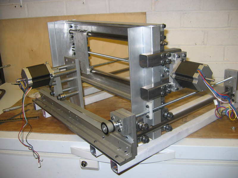
Stepper motors are everywhere in electronics these days.
There are two main types of stepper motors:
1. Bipolar motors. These have two coils and are controlled by changing the direction of the current flow through the coils in the proper sequence. These motors have only four wires and cannot be connected to this kit. See our Kit 1406 for a Bipolar Stepper driver Kit.
2. Unipolar motors. These have two center-tapped coils which are treated as four coils. These motors can have five, six or eight wires. Five-wire motors have the two center-taps commoned internally and brought out as one wire (Fig 1). Six-wire motors bring out each center-tap separately. The two center-taps need to be commoned externally (Fig 2). Eight-wire motors bring out both ends of each coil. The four �center-taps� are joined externally to form one wire. In each case the center-tap(s) are connected to a positive motor power supply. Unipolar motors may be connect as bipolar ones by not using the �+� wires.
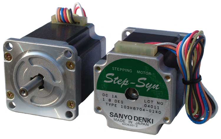
A stepper motor has no brushes or contacts. It is basically a synchronous motor with the magnetic field electronically switched to rotate the armature magnet around.
The Internet is where to get all the explanation about steppers. Just google �stepper motor� and you will find tens of sites. In particular, look for �Jones on Stepper motors� (it comes up top of the list when I did it just now) and read it. If you look at the other references you will find that the circuit in this kit has been around for many years in various forms. The latest publication was in Silicon Chip, 5/2002, and I have based this circuit on it.
|
Stepper Motor Driver Description
| |
This controller works in either free-standing or PC controlled mode.
In free-standing mode an internal square-wave oscillator based on IC2:B of the 4093 supplies timing pulses to the OSC output. The frequency of these pulses and thus the speed of the stepper motor is controlled by the trimpot VR1 (100K.) A series 1K resistor controls the maximum frequency. You may increase the value of this resistor for your own needs. These pulses are fed into the STEP input which is buffered and inverted by IC2:D. This helps prevent false triggering. Similarly, IC2:C buffers and inverts the DIRection input. A SPDT taking the input to +5VDC or ground controls the direction of rotation.
IC3:C and D (4030 or 4070 exclusive OR gates) invert the outputs available at Q and /Q outputs of each of the flip-flops (FF) IC4:A and IC4:B. The incoming step-pulses clock the FF, thus toggling the Q & /Q outputs and this turns the MOSFET�s on and off in sequence. The IRFZ44�s have a low on-resistance and can deliver up to 6A each without needing a heatsink.
Power to the stepper motor is connected to V+ and GND terminals as shown on the overlay. There is a separate power supply, KITV, to the 78L05 to power the IC�s. 9V � 12VDC will be sufficient. R2/C2 form a low-pass filter to filter fast-rise switching transients from the motor.
Note that some stepper motor texts say to use a 4070 instead of a 4030. We have not worked out why this is. Certainly our testing with the 4030�s showed no problems. I would like to hear from anyone who knows why this advice is sometime given.
In computer-controlled mode use the three pads with pins DIR, STEP and GND. Switch the SPDT switch to EXTernal. The direction SPDT has no effect in external mode.
|
| |
(Fig 1). Six-wire motors bring out each center-tap separately. The two center-taps need to be commoned externally

(Fig 2). Eight-wire motors bring out both ends of each coil. The four �center-taps� are joined externally to form one wire. In each case the center-tap(s) are connected to a positive motor power supply.
In
able to move the rotor you will need a driver.
Driver is a circuit that applies a voltage to
any of the four stator coils. Driver can be built
with IC such as ULN2003 (pictured on the circuit
diagram), four darlington transistors or four
power transistors such as 2N3055.
|
Assembly
| |
Note that after further testing we have changed the values of the trimpot and R1 from that shown on the PCB overlay.
Put the resistors and 4 links in first. Use the cutoff lengths from the resistors for the links. Add the other components as shown on the overlay. The IRFZ44 are placed back to back. The metal tabs are indicated by the bars on the overlay pattern. Slide the 3 terminal blocks together before inserting and soldering.
If you need to use a heatsink for the MOSFET�s then you will need insulating washers and bushes on each one to make sure they are electrically isolated from each other. |
Connecting Stepper Motor
| |
It is always fun connecting the motor correctly. Usually the motor has some indication of which wires are which. If not then use a multimeter to measure the resistance between pairs of wires and determine the layout. Connect the wires to the terminal block Apply power. Make sure the SPDT switch is set to INTernal. See if the motor is turning. If not then swap M1B & M2B wires only and check again. Now it should be turning. VR1 will vary the stepping speed. |
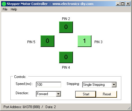
Stepper Motor Controller Software
| |
 |
Some
drivers might also come with a frequency
generator / timer that is used to control
a rotation speed (LM555 / NE555) and
digital IC such as 74LS194 that will
use pulses to generate a stepping mode.
In this project, on the other hand we
will use computer and a program to perform
that functionality. By using a computer
you will be able to do much more with
your stepper motor and most importantly
visualize how current is flowing through
individual coils.
The
program also includes features such
as easy to use graphical user interface,
allows you to precisely control the
motor speed and direction in real-time
and it also allows you to use different
stepping modes, such as single stepping,
high torque stepping and half stepping
modes.
|
The
program will work on any version of Windows
(98/ME/2000/XP). If it doesn't work than
you have to download and install Microsoft
.NET Framework.
 Download Stepper Motor Controller Download Stepper Motor Controller
|
|
|
|
|
| |
Accurate LC Meter
Build your own Accurate LC Meter (Capacitance Inductance Meter) and start making your own coils and inductors. This LC Meter allows to measure incredibly small inductances making it perfect tool for making all types of RF coils and inductors. LC Meter can measure inductances starting from 10nH - 1000nH, 1uH - 1000uH, 1mH - 100mH and capacitances from 0.1pF up to 900nF. The circuit includes an auto ranging as well as reset switch and produces very accurate and stable readings. |
|
PIC Volt Ampere Meter
Volt Ampere Meter measures voltage of 0-70V or 0-500V with 100mV resolution and current consumption 0-10A or more with 10mA resolution. The meter is a perfect addition to any power supply, battery chargers and other electronic projects where voltage and current must be monitored. The meter uses PIC16F876A microcontroller with 16x2 backlighted LCD. |
|
|
|
60MHz Frequency Meter / Counter
Frequency Meter / Counter measures frequency from 10Hz to 60MHz with 10Hz resolution. It is a very useful bench test equipment for testing and finding out the frequency of various devices with unknown frequency such as oscillators, radio receivers, transmitters, function generators, crystals, etc. |
|
1Hz - 2MHz XR2206 Function Generator
1Hz - 2MHz XR2206 Function Generator produces high quality sine, square and triangle waveforms of high-stability and accuracy. The output waveforms can be both amplitude and frequency modulated. Output of 1Hz - 2MHz XR2206 Function Generator can be connected directly to 60MHz Counter for setting precise frequency output. |
|
|
|
BA1404 HI-FI Stereo FM Transmitter
Be "On Air" with your own radio station! BA1404 HI-FI Stereo FM Transmitter broadcasts high quality stereo signal in 88MHz - 108MHz FM band. It can be connected to any type of stereo audio source such as iPod, Computer, Laptop, CD Player, Walkman, Television, Satellite Receiver, Tape Deck or other stereo system to transmit stereo sound with excellent clarity throughout your home, office, yard or camp ground. |
|
USB IO Board
USB IO Board is a tiny spectacular little development board / parallel port replacement featuring PIC18F2455/PIC18F2550 microcontroller. USB IO Board is compatible with Windows / Mac OSX / Linux computers. When attached to Windows IO board will show up as RS232 COM port. You can control 16 individual microcontroller I/O pins by sending simple serial commands. USB IO Board is self-powered by USB port and can provide up to 500mA for electronic projects. USB IO Board is breadboard compatible. |
|
|
|
|
ESR Meter / Capacitance / Inductance / Transistor Tester Kit
ESR Meter kit is an amazing multimeter that measures ESR values, capacitance (100pF - 20,000uF), inductance, resistance (0.1 Ohm - 20 MOhm), tests many different types of transistors such as NPN, PNP, FETs, MOSFETs, Thyristors, SCRs, Triacs and many types of diodes. It also analyzes transistor's characteristics such as voltage and gain. It is an irreplaceable tool for troubleshooting and repairing electronic equipment by determining performance and health of electrolytic capacitors. Unlike other ESR Meters that only measure ESR value this one measures capacitor's ESR value as well as its capacitance all at the same time. |
|
Audiophile Headphone Amplifier Kit
Audiophile headphone amplifier kit includes high quality audio grade components such as Burr Brown OPA2134 opamp, ALPS volume control potentiometer, Ti TLE2426 rail splitter, Ultra-Low ESR 220uF/25V Panasonic FM filtering capacitors, High quality WIMA input and decoupling capacitors and Vishay Dale resistors. 8-DIP machined IC socket allows to swap OPA2134 with many other dual opamp chips such as OPA2132, OPA2227, OPA2228, dual OPA132, OPA627, etc. Headphone amplifier is small enough to fit in Altoids tin box, and thanks to low power consumption may be supplied from a single 9V battery. |
|
|
|
|
|
Arduino Prototype Kit
Arduino Prototype is a spectacular development board fully compatible with Arduino Pro. It's breadboard compatible so it can be plugged into a breadboard for quick prototyping, and it has VCC & GND power pins available on both sides of PCB. It's small, power efficient, yet customizable through onboard 2 x 7 perfboard that can be used for connecting various sensors and connectors. Arduino Prototype uses all standard through-hole components for easy construction, two of which are hidden underneath IC socket. Board features 28-PIN DIP IC socket, user replaceable ATmega328 microcontroller flashed with Arduino bootloader, 16MHz crystal resonator and a reset switch. It has 14 digital input/output pins (0-13) of which 6 can be used as PWM outputs and 6 analog inputs (A0-A5). Arduino sketches are uploaded through any USB-Serial adapter connected to 6-PIN ICSP female header. Board is supplied by 2-5V voltage and may be powered by a battery such as Lithium Ion cell, two AA cells, external power supply or USB power adapter. |
|
200m 4-Channel 433MHz Wireless RF Remote Control
Having the ability to control various appliances inside or outside of your house wirelessly is a huge convenience, and can make your life much easier and fun. RF remote control provides long range of up to 200m / 650ft and can find many uses for controlling different devices, and it works even through the walls. You can control lights, fans, AC system, computer, printer, amplifier, robots, garage door, security systems, motor-driven curtains, motorized window blinds, door locks, sprinklers, motorized projection screens and anything else you can think of. |
|
|
|
|
|