| Stepper Motor Controller with Parallel Port Part's
List:
|
M42SP-5
Unipolar Stepper Motor
(or similar)
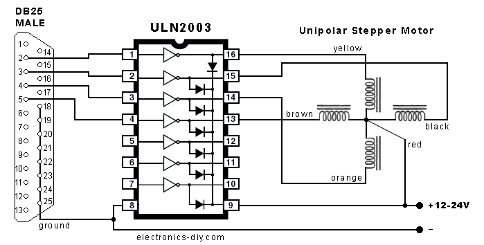
ULN2003 IC - stepper motor driver
DB25 Male connector |
|
|
|
| Technical
Specifications:
|
|
|
|
|
Stepper Motor Controller with Parallel Port
| |
This
is an easy to build stepper motor driver that will
allow you to precisely control a unipolar stepper
motor through your computer's parallel port. With
a stepper motor you can build a lot of interesting
gadgets such as robots, elevator, PCB drilling mill,
camera panning system, automatic fish feeder, etc.
If you have never worked with stepper motors before
you will surely have a lot of fun with this project.
|
How Stepper Motors Works?
| |
 Stepper
motors are very different from a regular DC motors.
Instead of spinning like DC motors do, stepper
motor steps at a specific resolution for each
pulse. The motor that we are using needs 48 steps
/ pulses just to complete a single revolution!
That should be enough to tell about its precision. Stepper
motors are very different from a regular DC motors.
Instead of spinning like DC motors do, stepper
motor steps at a specific resolution for each
pulse. The motor that we are using needs 48 steps
/ pulses just to complete a single revolution!
That should be enough to tell about its precision.
Another advantage of stepper motors is the fact
that their speed of rotation can be achieved almost
instantly even if you change the spinning direction.
Stepper motor consists of a rotor
- the permanent magnet that rotates inside, and
stator - four coils (north, east,
south, west) that are part of the case, and which
don't move. Rotor can be moved
by sequentially applying a pulsed DC voltage to
one or two coils at a time.
|
| |
In
able to move the rotor you will need a driver.
Driver is a circuit that applies a voltage to
any of the four stator coils. Driver can be built
with IC such as ULN2003 (pictured on the circuit
diagram), four darlington transistors or four
power transistors such as 2N3055.
|
Stepper Motor Connections
| |
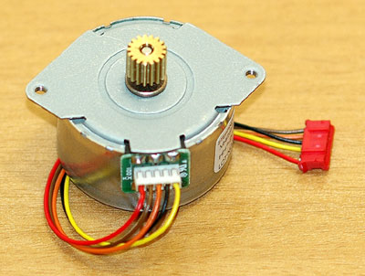 |
 Unipolar
motor should have five or six connections
depending on the model. If the motor has
six connections like the one pictured
above, you have to join pins 1 and 2 (red)
together and connect them to a (+) 12-24V
voltage supply. The remaining pins; a1
(yellow), b1 (black), a2 (orange), b2
(brown) should be connected to a driver
(ULN2003) as shown on the schematic. Unipolar
motor should have five or six connections
depending on the model. If the motor has
six connections like the one pictured
above, you have to join pins 1 and 2 (red)
together and connect them to a (+) 12-24V
voltage supply. The remaining pins; a1
(yellow), b1 (black), a2 (orange), b2
(brown) should be connected to a driver
(ULN2003) as shown on the schematic. |
|
| |
There
are several stepping modes that you can use
to drive the stepper motor.
1.
Single Stepping - the simplest mode
turns one coil ON at a time. 48 pulses are needed
to complete one revolution. Each pulse moves
rotor by 7.5 degrees. The
following sequence has to be repeated 12 times
for motor to complete one revolution.
|
Pulse |
Coil a1 |
Coil b1 |
Coil a2 |
Coil b2 |
1 |
ON |
|
|
|
2 |
|
ON |
|
|
3 |
|
|
ON |
|
4 |
|
|
|
ON |
2. High Torque Stepping - high
power / precision mode turns ON two coils on
at a time. 48 pulses are needed to complete
one revolution. Each pulse moves rotor by 7.5
degrees. The following
sequence has to be repeated 12 times for motor
to complete one revolution.
|
Pulse |
Coil a1 |
Coil b1 |
Coil a2 |
Coil b2 |
1 |
ON |
ON |
|
|
2 |
|
ON |
ON |
|
3 |
|
|
ON |
ON |
4 |
ON |
|
|
ON |
3.
Half Stepping - stepping is
doubled and
motor needs 96 pulses to complete one revolution.
Each pulse moves rotor by approximately 3.75
degrees. Notice the mix of single stepping mode
(lighter green) and high torque mode (darker
green).
| Pulse |
Coil
a1 |
Coil
b1 |
Coil
a2 |
Coil
b2 |
1 |
ON |
|
|
|
2 |
ON |
ON |
|
|
| 3 |
|
ON |
|
|
4 |
|
ON |
ON |
|
5 |
|
|
ON |
|
6 |
|
|
ON |
ON |
7 |
|
|
|
ON |
8 |
ON |
|
|
ON |
| |
- single stepping mode, normal
strength, quiet |
| |
- high torque mode, high strength, slightly
louder |
|
Stepper Motor Controller Software
| |
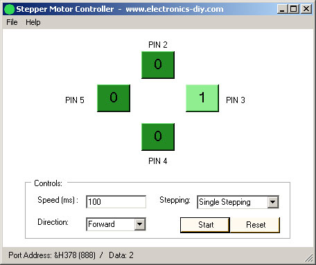 |
Some
drivers might also come with a frequency
generator / timer that is used to control
a rotation speed (LM555 / NE555) and
digital IC such as 74LS194 that will
use pulses to generate a stepping mode.
In this project, on the other hand we
will use computer and a program to perform
that functionality. By using a computer
you will be able to do much more with
your stepper motor and most importantly
visualize how current is flowing through
individual coils.
The
program also includes features such
as easy to use graphical user interface,
allows you to precisely control the
motor speed and direction in real-time
and it also allows you to use different
stepping modes, such as single stepping,
high torque stepping and half stepping
modes.
|
The
program will work on any version of Windows
(98/ME/2000/XP). If it doesn't work than
you have to download and install Microsoft
.NET Framework.
 Download Stepper Motor Controller Download Stepper Motor Controller
|
|
|
|
|
| |
Accurate LC Meter
Build your own Accurate LC Meter (Capacitance Inductance Meter) and start making your own coils and inductors. This LC Meter allows to measure incredibly small inductances making it perfect tool for making all types of RF coils and inductors. LC Meter can measure inductances starting from 10nH - 1000nH, 1uH - 1000uH, 1mH - 100mH and capacitances from 0.1pF up to 900nF. The circuit includes an auto ranging as well as reset switch and produces very accurate and stable readings. |
|
PIC Volt Ampere Meter
Volt Ampere Meter measures voltage of 0-70V or 0-500V with 100mV resolution and current consumption 0-10A or more with 10mA resolution. The meter is a perfect addition to any power supply, battery chargers and other electronic projects where voltage and current must be monitored. The meter uses PIC16F876A microcontroller with 16x2 backlighted LCD. |
|
|
|
60MHz Frequency Meter / Counter
Frequency Meter / Counter measures frequency from 10Hz to 60MHz with 10Hz resolution. It is a very useful bench test equipment for testing and finding out the frequency of various devices with unknown frequency such as oscillators, radio receivers, transmitters, function generators, crystals, etc. |
|
1Hz - 2MHz XR2206 Function Generator
1Hz - 2MHz XR2206 Function Generator produces high quality sine, square and triangle waveforms of high-stability and accuracy. The output waveforms can be both amplitude and frequency modulated. Output of 1Hz - 2MHz XR2206 Function Generator can be connected directly to 60MHz Counter for setting precise frequency output. |
|
|
|
BA1404 HI-FI Stereo FM Transmitter
Be "On Air" with your own radio station! BA1404 HI-FI Stereo FM Transmitter broadcasts high quality stereo signal in 88MHz - 108MHz FM band. It can be connected to any type of stereo audio source such as iPod, Computer, Laptop, CD Player, Walkman, Television, Satellite Receiver, Tape Deck or other stereo system to transmit stereo sound with excellent clarity throughout your home, office, yard or camp ground. |
|
USB IO Board
USB IO Board is a tiny spectacular little development board / parallel port replacement featuring PIC18F2455/PIC18F2550 microcontroller. USB IO Board is compatible with Windows / Mac OSX / Linux computers. When attached to Windows IO board will show up as RS232 COM port. You can control 16 individual microcontroller I/O pins by sending simple serial commands. USB IO Board is self-powered by USB port and can provide up to 500mA for electronic projects. USB IO Board is breadboard compatible. |
|
|
|
|
ESR Meter / Capacitance / Inductance / Transistor Tester Kit
ESR Meter kit is an amazing multimeter that measures ESR values, capacitance (100pF - 20,000uF), inductance, resistance (0.1 Ohm - 20 MOhm), tests many different types of transistors such as NPN, PNP, FETs, MOSFETs, Thyristors, SCRs, Triacs and many types of diodes. It also analyzes transistor's characteristics such as voltage and gain. It is an irreplaceable tool for troubleshooting and repairing electronic equipment by determining performance and health of electrolytic capacitors. Unlike other ESR Meters that only measure ESR value this one measures capacitor's ESR value as well as its capacitance all at the same time. |
|
Audiophile Headphone Amplifier Kit
Audiophile headphone amplifier kit includes high quality audio grade components such as Burr Brown OPA2134 opamp, ALPS volume control potentiometer, Ti TLE2426 rail splitter, Ultra-Low ESR 220uF/25V Panasonic FM filtering capacitors, High quality WIMA input and decoupling capacitors and Vishay Dale resistors. 8-DIP machined IC socket allows to swap OPA2134 with many other dual opamp chips such as OPA2132, OPA2227, OPA2228, dual OPA132, OPA627, etc. Headphone amplifier is small enough to fit in Altoids tin box, and thanks to low power consumption may be supplied from a single 9V battery. |
|
|
|
|
|
Arduino Prototype Kit
Arduino Prototype is a spectacular development board fully compatible with Arduino Pro. It's breadboard compatible so it can be plugged into a breadboard for quick prototyping, and it has VCC & GND power pins available on both sides of PCB. It's small, power efficient, yet customizable through onboard 2 x 7 perfboard that can be used for connecting various sensors and connectors. Arduino Prototype uses all standard through-hole components for easy construction, two of which are hidden underneath IC socket. Board features 28-PIN DIP IC socket, user replaceable ATmega328 microcontroller flashed with Arduino bootloader, 16MHz crystal resonator and a reset switch. It has 14 digital input/output pins (0-13) of which 6 can be used as PWM outputs and 6 analog inputs (A0-A5). Arduino sketches are uploaded through any USB-Serial adapter connected to 6-PIN ICSP female header. Board is supplied by 2-5V voltage and may be powered by a battery such as Lithium Ion cell, two AA cells, external power supply or USB power adapter. |
|
200m 4-Channel 433MHz Wireless RF Remote Control
Having the ability to control various appliances inside or outside of your house wirelessly is a huge convenience, and can make your life much easier and fun. RF remote control provides long range of up to 200m / 650ft and can find many uses for controlling different devices, and it works even through the walls. You can control lights, fans, AC system, computer, printer, amplifier, robots, garage door, security systems, motor-driven curtains, motorized window blinds, door locks, sprinklers, motorized projection screens and anything else you can think of. |
|
|
|
|
|