| |
12V Fluorescent Light Inverter |
|
This is a low voltage 12V fluorescent inverter for powering two 20W or single 40W fluorescent tube. It's a circuit you can put together from junk box components and is a very simple to build. The transformer is hand-wound on a ferrite rod from an old transistor radio and the winding wire can be salvaged from an old transformer. The cost of powering the circuit is about 22 watts and this will produce the same light output as 60 watt incandescent light bulb.
With a normal fluoro operating on the 240v mains, a ballast (or choke) is needed in series with the tube to limit the current after the tube has "struck". This ballast dissipates about 10-20 watts for a 20 watt tube and reduces the efficiency of the circuit.
If the ballast is replaced with an electronic circuit and high-frequency transformer, the losses are less than 5 watts. Furthermore, if we do not drive the tube as hard as the 240v version we can get even better efficiency.
The size of tube, you will need, will depend on the area you wish to illuminate and the battery capacity you have available, however it is important to realise that the higher wattage tubes offer the greatest efficiency.
This is because they have a longer length and larger diameter (than say an 8 watt tube) and give more light over a larger area. That's why we have concentrated our design on the 40 watt tube. You can get plenty of circuits and devices that power the 4, 6 and 8 watt tubes but nothing has been done for the 40 watt variety.
There is another range of tubes, commonly called the "compact fluoro" or high efficiency fluoro. These are a folded fluorescent tube having a rating of either 11 watts, 13watts or 18watts. They are not covered in this project as they are expensive to boy and more difficult to drive. They are actually driven VERY HARD and if you feel one after it has been turned on for a few minutes you will find the tube is quite warm.
They are not really suitable for indoor use as they take a while to come on and don't give enough illumination for an average room. We have tried the whole range of these tubes and come to the conclusion that they are only suitable for outdoor use as a decorative lamp or for partially illuminating a dark area.
This is one of those situations where the old-style product is the best. I think you will find that the glitter of the compact lamp has almost faded by now as the public has come to realize they are not the whiz bang invention of the century and have not taken over any of the areas already serviced by the tungsten lamp or standard fluoro.
After all, you can buy a 100watt globe for less than $1.00 and a compact lamp costs about $20.00. It will take more than 5 years for the savings in electricity to equal the cheap 100 watt globe.
The one problem that lets compact lamps down is the electronic circuitry. The electrolytics in the base are driven very hard and tend to dry out after a few years. We have found lots of discarded bases (with tube) with this problem.
Apart from this, the fluorescent lamp has a number of advantages over incandescent lighting. The main one is efficiency.
This is due to the fact that it's a cold light, in comparison to incandescent light where the light is produced by the heating of a piece of wire.
The other advantage is the light does not come from a point source and thus it is more-evenly spread over a larger area.
Fluorescent lighting is approximately 400% more efficient than incandescent lighting (50 Lumens/watt compared to 12 Lumens/watt for a 100 watt tungsten lamp), although there are some losses in the ballast. A 20 watt tube (plus 10-20 watts for the ballast) gives the same light output as a 100 watt lamp, when it is heavily driven in the 240v mode.
For a normal household, the lighting component of the electricity bill is only a fraction of the total and doesn't warrant a house to be converted to fluorescent lighting.
But if you are considering setting up a home in a remote area, where mains electricity is not available, you will appreciate the advantage of high-efficiency lighting.
With modern electronic circuits, fluorescent lamps can be designed to operate very efficiently and with this project you can build the circuit yourself and operate it from a 12v supply.
THE 12V SUPPLY
In any low-voltage situation the greatest component of consumption is lighting. This is because all the other appliances have been converted to some other form of energy. The fridge has been converted to gas. the toaster has been thrown out, the jug has been changed to a saucepan or kettle on a fuel stove and the electric fry pan has been forgotten.
All that has been left is the lighting and a few small appliances such as the washing machine, portable TV and drill (12v rechargeable type).
When considering the sort of lighting you need, you must take into account the type of work you will be carrying out such as eating, reading, repairing etc.
For some of these, the light from a camp-fire will be sufficient while for repair work you will need the highest level of illumination.
To provide the required level there are two choices. The standard 12v globe, and the fluorescent tube.
I have not considered the use of gas lighting as they remove the oxygen from the air, produce a lot of heat and are potentially very dangerous.
If you need to carry out fine, detailed work, you will need a standard 12v globe or even a 50 watt halogen lamp.
However for general room illumination, a 20 watt fluorescent will be adequate.
Let's see how we can make a 20 watt inverter.
The project we will be describing is not designed to drive any of the compact (or folded) fluorescent tubes as they are driven much harder than ordinary tubes and get quite warm after only a few minutes of operation.
This heating represents wasted energy and in this project we are trying to save as much energy as possible.
Folded tubes are also less efficient than ordinary straight tubes as they have two or four tubes running beside each other and when they are illuminated, some of the light from one tube will hit against the walls of the others and be lost.
The folded tube is not suitable for indoor use. All the tubes I have bought have been a failure. Some took a long time to come on - up to 10 seconds to "strike."
The other disappointment is the weak output for the first 10 minutes or so. They take about 10 minutes to "get going."
I have an 18 watt compact lamp in my room at the moment and cannot read the pages I am preparing. It's another invention that has "missed the bus" -they are just not quite good enough.
I am going to replace it with a 100 watt globe and come back.
While in the process of changing the globe, I compared the 18 watt compact fluoro with our circuit driving two 20 watt tubes and found them to almost the same. They are equivalent to a 60 or 75 watt clear globe and is perfectly ok for general lighting in a room.
There is an enormous difference between the circuit for a fluoro operating on 240v AC and one that operates on 12v DC.
20 WATT FLUORO
The wattage of a fluorescent tube is a characteristic of its size and vice versa; the wattage determines the size. That's why a 20 watt tube is 2 feet long and a 40 watt tube is 4 feet long.
The design of a tube is a complex mathematical equation (a lot of experimentation has gone into its design).
The tubes are filled with a gaseous mixture that produces ultra-violet light when operating and this light hits against the walls of the tube to excite the coating on the inside to produce visible light.
The gas and the coating are all poisonous and the emission of the ultraviolet waveform from an uncoated tube is quite dangerous to the eyes, so experimenting with tubes other than operating them as per this project is to be avoided.
You can buy uncoated tubes (called ultraviolet tubes) for lighting effects, EPROM erasing, special heating, and germicidal applications. Do not use any of these tubes in this project as the voltage we are producing will create different effects and damage your eyes.
12v INVERTER
Now for the 12v version.
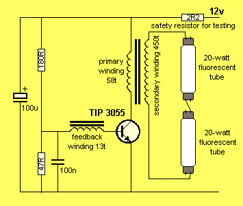
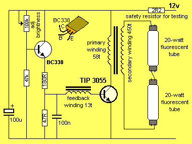
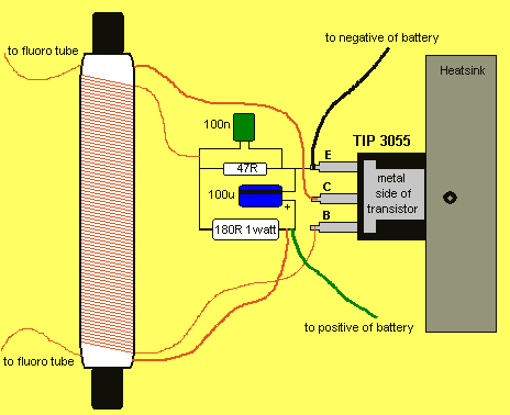
The circuit doesn't require many components but its operation is quite complex. The clever component is the transformer. It performs 3 functions.
Firstly it is acting as a feedback component for the transistor to create an oscillator circuit. Secondly it is providing a high voltage (over 1 000 volts) to strike the tube and keep it struck and thirdly it is supplying spikes of energy to illuminate the tube.
The circuit is shown in figure 1 and we will take a detailed look at how the transformer carries out the three functions.
The transformer in this project is not a lethal device as the output wattage is slightly below the value that produces electrocution. However the output is in excess of 1,000v and the ends of the secondary winding should not be touched when the transformer is operating.
To get a shock you must touch both
ends at the same time - it is not sufficient to touch one end and any other part of the circuit as the secondary is an isolated winding.
Even a simple transformer such as the one we are winding in this project will demonstrate a number of interesting features. One of them is the ability to step-up a voltage. This is the main purpose in this project as we require a voltage of approximately 1,000v to strike the tube.
Another interesting feature is the availability to get positive or negative voltage (phase) from a separate winding on the transformer, simply by connecting the winding around one way or the other. In this project we connect the winding to get positive feedback so that a single transistor will drive the circuit.
HOW THE OSCILLATOR WORKS
The oscillator works on positive feedback. This positive feedback comes from a separate 13 turn winding on the transformer called the feedback winding.
The cycle starts by turning on the transistor a fair bit via the 180R resistor on the base and this causes current to flow in the primary winding. The flow of current causes magnetic flux to be produced by the winding and this passes through the ferrite core. The feedback winding is also wound around the core and the magnetic lines pass through this winding and produce a voltage.
The winding is connected to the transistor so that the voltage from the winding ASSISTS the voltage from the 180R resistor and causes the transistor to turn on harder.
Thus more current flows through the primary winding and the magnetic flux increases. This causes more voltage to be produced in the feedback winding and the transistor turns on even harder.
This continues until the transistor is fully turned ON and maximum current is flowing in the primary winding.
Now comes the important part.
Even though maximum current is flowing in the primary winding and maximum flux is produced in the core, this flux is a steady flux and not an increasing flux.
The only time a voltage is produced in a secondary (or feedback) winding is when the flux is INCREASING (or decreasing). When the flux is stationary, the voltage in any of these windings ceases to be produced.
Thus we come to a point in the cycle where the current in the primary is a maximum but the voltage in the feedback winding is zero.
The only current flowing into the base of the transistor comes from the turn on resistor but this is note enough to fully turn the transistor ON and so the transistor turns off a small amount.
This has the effect of reducing the flux in the ferrite rod and we now have a situation where the flux is DECREASING. This changes the situation in the feedback winding. The voltage in the feedback winding is now produced in the OPPOSITE DIRECTION and the transistor begins to turn off even more.
The magnetic flux begins to collapse very quickly and this produces a very high reverse voltage on the base of the transistor (up to about 25v) to turn the transistor off completely.
This is how we get a positive and negative voltage for the transistor.
This is quite an amazing achievement as the voltage through the primary doesn't change direction - it merely increases and decreases in value - but the voltage from any of the other windings changes direction!
The collapsing magnetic flux cuts the turns of the secondary winding and produces a voltage of about 2.5v per turn in the 450 turns, making a total of about 1 ,000 appearing across the ends of the tube. This is sufficient to strike the tube and as we mentioned above, the resistance (or impedance) of the tube reduces as more current flows. In our case the voltage across the tube is about 400v (this voltage depends on how hard the tube is driven and is riot a fixed value).
When the magnetic flux has almost fully been converted to electrical energy, the 180R turn-on resistor on the base of the transistor starts the cycle over again.
The voltages produced by the transformer are very spiky and the gas in a fluorescent tube is very quick to react to these spikes. The gas produces ultraviolet light that strikes the fluorescent material on the inside of the tube and causes it to produce visible light.
The tube forms part of the load for the transformer and has an effect on quenching the spikes to the transistor so it is not advisable to operate the transformer without the tube connected.
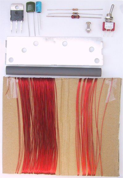
PARTS LIST
1 – 2R2 1/4watt (for testing)
1 - 47R 1/4watt
1 - 180R 1watt
1 - 47k
1 - 100k mini rim pot
1 - 100ngreencap
1 - 100u 16v electrolytic
1 - BC338 transistor
1 - TIP 3055 transistor
1 - on/off switch
1 - 12mm bolt and nut for transistor
1 - heat-sink 5cm x 10cm
1 - ferrite rod 10mm dia x 8m long
1 - 30m winding wire .28mm dia
1 - 4m winding wire .61 mm dia
(wire diameters are NOT critical)
1 - insulation tape either sticky tape
or masking tape
1 - interlayer insulation - paper
Extras:
2 - 20 watt fluorescent tubes
1 - box to house project
1 - 6m of figure-8 flex to go between inverter and tube(s)
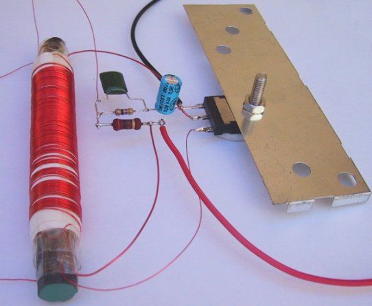
WINDING THE TRANSFORMER
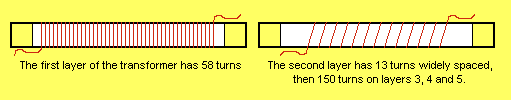
The ferrite core of the transformer is an antenna rod from an old transistor radio. You could use a slab antenna but we have chosen a 10mm diameter rod, 8cm long and the first winding to be wound on it is called the primary.
This consists of 58 turns of wire spaced slightly apart so that is occupies the centre 6cm of the rod. The first thing to do is wind two layers of insulation around the rod so that the wire does not touch the rod and create a short.
Leave the first 8 - 10cm of wire and start winding with the thick .61mm wire. But firstly hold the end of the wire in place with a short piece of sticky tape folded over itself and stuck along the length of the rod, where the winding is to be placed. Continue winding and fix the other end in a similar manner, leaving 8 - 10 cm for connecting to the rest of the components.
Place one layer of paper over this winding and secure both the start and end of the paper with sticky tape. Make sure this insulating paper is tight by rolling it like a cigarette before sticky-taping.
The next layer is called the feedback winding and consists of 13 turns of the thin .28mm wire, wound in a spiral fashion so that it takes up the full length of the 6cm.
Terminate both the start and finish of the winding with sticky tape to prevent it unwinding. Cover this with a layer of insulation.
Now, for the final winding, called the secondary.
This consists of 450 turns of .28mm wire, wound in 3 layers of 150 turns.
The winding does not have to be neat and you could quite easily jumble-wind the turns and it would work perfectly ok, however there are two factors to remember.
The voltage between the start and finish of this winding will be about 1,000 volts and the insulation on the wire is only about 100v. So the start and the finish must not be near each other. This also applies to most of the other turns so the best way to prevent the inner-turn sorts is to carefully wind the turns side-by side.
This also produces the best results.
Leave 8 - 10 cm of wire and hold the start in place with a piece of sticky-tape folded over itself and stuck to the insulation. Wind 150 turns neatly across the 6cm of the transformer and hold the last turn in place with sticky tape before placing a layer of insulation over the winding. Continue with the next layer and one more, making a total of 450 turns.
Cover the last layer with insulation, tin the ends of each of the windings with a hot soldering iron and plenty of solder and the transformer is complete.
CONNECTING THE TRANSFORMER
The transformer has 6 wires.
The two high voltage wires from the secondary can be connected around either way to the tubes.
Either lead of the primary, can be connected to the collector, and the other end connects to the positive of the battery and 180R resistor. Now comes the difficult part.
The feedback winding must be connected to the base and the join of the resistors so that the transistor gets positive feedback. You can do this by marking the start of the primary winding and the start of the feedback winding and connecting them in a particular way, but if you are wrong, a very high current will flow and the transistor will be damaged. We have devised a fail-safe method that doesn't rely on you having to remember which is the start of each of the windings, or the direction of the winding. It's called trial and error with safety resistor.
Place the 2R2 safety resistor in the positive line as shown in the circuit diagram and connect the feedback winding any way you wish. Turn the project ON AND OFF very quickly. If the fluoro's don't come on immediately, the feedback winding is around the wrong way. The safety resistor will only allow 5amps to flow thorough the circuit and the transistor will not be damaged.
Related Links
Downloads
12V Fluorescent Light Inverter - Link
|
|
|
| |
Accurate LC Meter
Build your own Accurate LC Meter (Capacitance Inductance Meter) and start making your own coils and inductors. This LC Meter allows to measure incredibly small inductances making it perfect tool for making all types of RF coils and inductors. LC Meter can measure inductances starting from 10nH - 1000nH, 1uH - 1000uH, 1mH - 100mH and capacitances from 0.1pF up to 900nF. The circuit includes an auto ranging as well as reset switch and produces very accurate and stable readings. |
|
PIC Volt Ampere Meter
Volt Ampere Meter measures voltage of 0-70V or 0-500V with 100mV resolution and current consumption 0-10A or more with 10mA resolution. The meter is a perfect addition to any power supply, battery chargers and other electronic projects where voltage and current must be monitored. The meter uses PIC16F876A microcontroller with 16x2 backlighted LCD. |
|
|
|
60MHz Frequency Meter / Counter
Frequency Meter / Counter measures frequency from 10Hz to 60MHz with 10Hz resolution. It is a very useful bench test equipment for testing and finding out the frequency of various devices with unknown frequency such as oscillators, radio receivers, transmitters, function generators, crystals, etc. |
|
1Hz - 2MHz XR2206 Function Generator
1Hz - 2MHz XR2206 Function Generator produces high quality sine, square and triangle waveforms of high-stability and accuracy. The output waveforms can be both amplitude and frequency modulated. Output of 1Hz - 2MHz XR2206 Function Generator can be connected directly to 60MHz Counter for setting precise frequency output. |
|
|
|
BA1404 HI-FI Stereo FM Transmitter
Be "On Air" with your own radio station! BA1404 HI-FI Stereo FM Transmitter broadcasts high quality stereo signal in 88MHz - 108MHz FM band. It can be connected to any type of stereo audio source such as iPod, Computer, Laptop, CD Player, Walkman, Television, Satellite Receiver, Tape Deck or other stereo system to transmit stereo sound with excellent clarity throughout your home, office, yard or camp ground. |
|
USB IO Board
USB IO Board is a tiny spectacular little development board / parallel port replacement featuring PIC18F2455/PIC18F2550 microcontroller. USB IO Board is compatible with Windows / Mac OSX / Linux computers. When attached to Windows IO board will show up as RS232 COM port. You can control 16 individual microcontroller I/O pins by sending simple serial commands. USB IO Board is self-powered by USB port and can provide up to 500mA for electronic projects. USB IO Board is breadboard compatible. |
|
|
|
|
ESR Meter / Capacitance / Inductance / Transistor Tester Kit
ESR Meter kit is an amazing multimeter that measures ESR values, capacitance (100pF - 20,000uF), inductance, resistance (0.1 Ohm - 20 MOhm), tests many different types of transistors such as NPN, PNP, FETs, MOSFETs, Thyristors, SCRs, Triacs and many types of diodes. It also analyzes transistor's characteristics such as voltage and gain. It is an irreplaceable tool for troubleshooting and repairing electronic equipment by determining performance and health of electrolytic capacitors. Unlike other ESR Meters that only measure ESR value this one measures capacitor's ESR value as well as its capacitance all at the same time. |
|
Audiophile Headphone Amplifier Kit
Audiophile headphone amplifier kit includes high quality audio grade components such as Burr Brown OPA2134 opamp, ALPS volume control potentiometer, Ti TLE2426 rail splitter, Ultra-Low ESR 220uF/25V Panasonic FM filtering capacitors, High quality WIMA input and decoupling capacitors and Vishay Dale resistors. 8-DIP machined IC socket allows to swap OPA2134 with many other dual opamp chips such as OPA2132, OPA2227, OPA2228, dual OPA132, OPA627, etc. Headphone amplifier is small enough to fit in Altoids tin box, and thanks to low power consumption may be supplied from a single 9V battery. |
|
|
|
|
|
Arduino Prototype Kit
Arduino Prototype is a spectacular development board fully compatible with Arduino Pro. It's breadboard compatible so it can be plugged into a breadboard for quick prototyping, and it has VCC & GND power pins available on both sides of PCB. It's small, power efficient, yet customizable through onboard 2 x 7 perfboard that can be used for connecting various sensors and connectors. Arduino Prototype uses all standard through-hole components for easy construction, two of which are hidden underneath IC socket. Board features 28-PIN DIP IC socket, user replaceable ATmega328 microcontroller flashed with Arduino bootloader, 16MHz crystal resonator and a reset switch. It has 14 digital input/output pins (0-13) of which 6 can be used as PWM outputs and 6 analog inputs (A0-A5). Arduino sketches are uploaded through any USB-Serial adapter connected to 6-PIN ICSP female header. Board is supplied by 2-5V voltage and may be powered by a battery such as Lithium Ion cell, two AA cells, external power supply or USB power adapter. |
|
200m 4-Channel 433MHz Wireless RF Remote Control
Having the ability to control various appliances inside or outside of your house wirelessly is a huge convenience, and can make your life much easier and fun. RF remote control provides long range of up to 200m / 650ft and can find many uses for controlling different devices, and it works even through the walls. You can control lights, fans, AC system, computer, printer, amplifier, robots, garage door, security systems, motor-driven curtains, motorized window blinds, door locks, sprinklers, motorized projection screens and anything else you can think of. |
|
|
|