| |
Adjustable Constant Current Load |
|
An adjustable power load is a piece of test equipment that often comes handy in the development of a certain electronics projects. For example, when you are building a power supply, it will come a time when you need to "simulate" a load to see how well your design performs as the load varies. Adding power resistors to the output can sometimes do in a pinch, but often you will not have the right resistor value handy with the right power rating for the test. This is where an adjustable electronic load comes handy. In this article, I'll show how you can build one using common components available to the electronics hobbyist.

The circuit
Constant current "dummy load" designs built around the venerable LM324 quad OPAMP have become quite popular in the hobbyist community. The basic concept has been around for a long time though, and it's essentially an OPAMP based current source design. The current source portion of the circuit below is very similar to Dave's design. It always bothered me though that the original design didn't use the four OPAMPs in the LM324, and that there was limited protection in the circuit. Therefore, I decided to use one of the two "spare" OPAMPs for thermal overload protection and another to activate a cooling fan. This approach should result in a more reliable design which is an important consideration for test equipment.
Figure 1 shows the circuit schematic. The "Current Source" portion should be familiar to anyone that has seen similar designs on the web. The U2D OPAMP is a voltage follower that ensures the voltage at the 0.1 Ohm resistor "follows" the voltage applied to its non-inverting input. Therefore the current at the output through the 0.1 Oh resistor is I = Vi / (0.1) = 10 x Vi. I decided to use a 0.1 Ohm resistor (instead of the common 1 Ohm design) to allow larger currents. The smaller resistor value reduces the power dissipated in the resistor for a given output current. Furthermore, the source-to-ground voltage is also reduced thus ensuring that VGS is kept well above the MOSFET's threshold voltage for all practical operation conditions. I used two 50N06 N-channel MOSFETs in parallel to reduce the total Ron and improve reliability. In this design, the maximum current should be about 7A and it is limited by the 5W resistor I used; not by the MOSFETs. Larger currents can be achieved with a resistor capable of 10 or 20 W dissipation (which I didn't have handy). The input voltage should not exceed 60V (maximum VDS for these MOSFETs). As an added protection measure, I added a power MOV from the input to ground to protect the MOSFETs against high-voltage transients.
The U2A OPAMP is a voltage follower buffering the "set voltage" from the resistive divider formed by the 1 M resistor and the multi-turn potentiometer RV1. If a multi-turn pot is not available, you can use two single turn pots in series instead (100K and 10K for example). The U2A output drives another resistive divider before driving the panel meter. This was needed in my case to "calibrate" the panel meter independently for voltage and current readings. If only one reading is needed, this portion can be skipped. The switch SW2 switches between voltage and current readings. I found this to be very useful in normal operation so you can quickly calculate the power dissipation. Switch SW2 allows you to see the current "programmed" by the resistive divider even if no load is connected. This is a "convenience" feature I saw implemented in another design posted in the eevblog forum that turns-out to be quite important. Without this switch, one cannot know exactly the "programmed" load current until the input terminals are connected. In the best-case scenario this is just an annoyance. In the worst-case scenario it can actually be quite dangerous for the external circuit, as you can inadvertently apply an excessive load to your supply under test !
As mentioned in the introduction, the two "spare" OPAMPs are used for protection and cooling fan control. U2C forms a simple comparator between the voltage set by the thermistor and R8 voltage divider and the R5, R6 voltage divider. The hysteresis is controlled by the positive feedback provided by R4. The thermistor is placed in contact with the MOSFET's heatsink and its resistance decreases as the temperature increases. When the temperature exceeds the set threshold, the U2C output goes High. This turns-on the BS170 MOSFET and immediately forces the control voltage at the U2D input to ground thus shutting down the current source and protecting the circuit. I calculated the threshold set by R5 and R6 for my particular application based on temperature measurements at the MOSFET case. For a more generic approach, you can replace R5 and R6 with an adjustable trim-pot and set the right threshold for your design. Ensure that the protection trips when the MOSFET's junction temperature is slightly below the absolute maximum rating specified in the data-sheet. In normal operation, the BS170 is OFF and very little current flows through the Drain (leakage current mostly) so it doesn't affect the circuit. The LED D2 signals the user when the overload protection is activated and was mounted in the front panel.
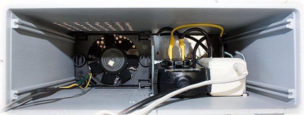
The U2B OPAMP is also a voltage comparator with hysteresis and is used to control a 12V fan (re-used from an old PC power supply). A 1N4001 diode protects the BS170 MOSFET against inductive kick-back voltages. The temperature threshold for the fan activation, controlled by RV2, should obviously be lower than the overload protection threshold. One could argue that the whole fan control circuit is not needed and that the fan should always be on. While this is certainly a valid approach, I prefer not to deal with the fan noise when the power dissipated in the load is low and found this circuit to accomplish this goal quite nicely.
Lessons Learned
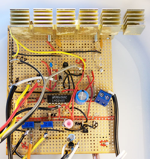
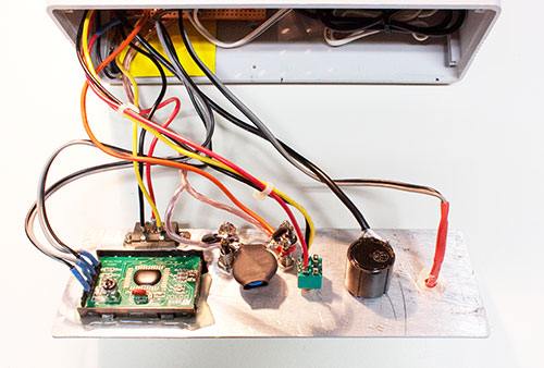
I decided to build this circuit in a simple Perfboard rather than designing a dedicated pcb. In retrospect, this was a mistake. As I later learned, the parasitic capacitance in this layout made the circuit quite susceptible to oscillation. To understand how to "tame" the oscillation, I ended-up reading quite a bit on stability as a "refresher course", and actually learned a bit (there's always a silver lining). For those interested in the topic, I recommend Ron Mancini's excellent Apnote "Op Amp Stability and input capacitance" from Texas Instruments. R7 and C5 was my first approach at increasing the phase margin but proved insufficient. I ended-up using a "heavy-handed", dominant-pole compensation technique by adding capacitors C6 and C7 to the 50N06 Gates. This may be overkill in your particular design and layout, but it's an effective solution when everything else fails.
The second lesson I learned is related to ground currents (which could have been avoided with a good PCB as well). A "mysterious" increase in the measured current in the panel meter was seen at first whenever the fan activated. Since the fan is not powered from the load input, this was quite unexpected. After some debugging, I found that the ground return current for the fan was flowing through the same path as the ground return for POT1. Since the voltage at this potentiometer is very small (a side effect of the divider network and the small 0.1 Ohm sense resistor I chose) this was adding a voltage drop through the ground plane that was visible in the panel meter. Adding an additional ground path directly from the ground of Q2 to the power ground input solved the issue. This is part of the fun in building these circuits; you learn a lot by making mistakes!
Assembly
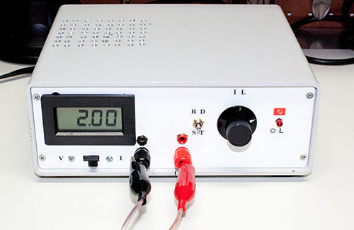
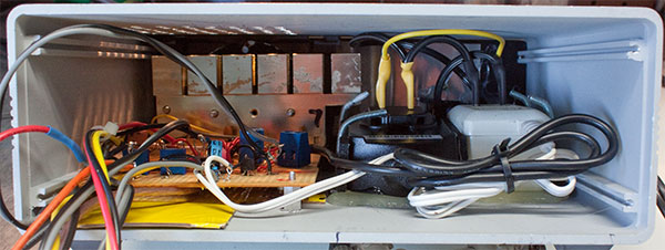
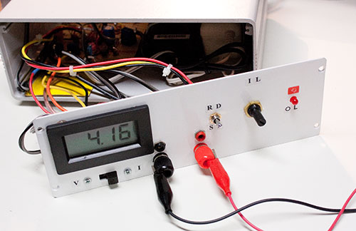
I'm not particularly "mechanically inclined", but I'm quite proud of the way the assembly turned out this time. I re-used an old parallel-port switch aluminum box as an enclosure for the project. This is a very good quality box with plenty of space for components. I used some old AC/DC adapters to supply the 12V for the main circuit and the 9V for the panel meter (yes; it's one of those meters that requires a separate ground so I couldn't use a LM317 to generate the 9V from the 12V). The front panel assembly is depicted in figure 5. The panel meter is on the left whereas the multi-turn pot is on the right. Notice the big MOV soldered right at the input terminals to prevent voltage surges from propagating further down the circuit.
Putting it all together
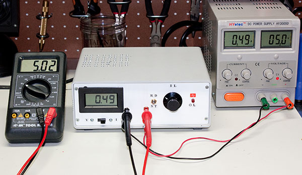
Here's a typical test setup (see Figure 8). The DUT is the power supply on the right set for 5V. The load in this example is drawing only 0.49A. Using the "measurement" terminals, I connected a multimeter right at the load input, so that load current and voltage are monitored simultaneously. This is a relatively simple and fun project to build. It should prove useful in my lab for years to come.
Related Links
Downloads
Adjustable Constant Current Load - Link
|
|
|
| |
Accurate LC Meter
Build your own Accurate LC Meter (Capacitance Inductance Meter) and start making your own coils and inductors. This LC Meter allows to measure incredibly small inductances making it perfect tool for making all types of RF coils and inductors. LC Meter can measure inductances starting from 10nH - 1000nH, 1uH - 1000uH, 1mH - 100mH and capacitances from 0.1pF up to 900nF. The circuit includes an auto ranging as well as reset switch and produces very accurate and stable readings. |
|
PIC Volt Ampere Meter
Volt Ampere Meter measures voltage of 0-70V or 0-500V with 100mV resolution and current consumption 0-10A or more with 10mA resolution. The meter is a perfect addition to any power supply, battery chargers and other electronic projects where voltage and current must be monitored. The meter uses PIC16F876A microcontroller with 16x2 backlighted LCD. |
|
|
|
60MHz Frequency Meter / Counter
Frequency Meter / Counter measures frequency from 10Hz to 60MHz with 10Hz resolution. It is a very useful bench test equipment for testing and finding out the frequency of various devices with unknown frequency such as oscillators, radio receivers, transmitters, function generators, crystals, etc. |
|
1Hz - 2MHz XR2206 Function Generator
1Hz - 2MHz XR2206 Function Generator produces high quality sine, square and triangle waveforms of high-stability and accuracy. The output waveforms can be both amplitude and frequency modulated. Output of 1Hz - 2MHz XR2206 Function Generator can be connected directly to 60MHz Counter for setting precise frequency output. |
|
|
|
BA1404 HI-FI Stereo FM Transmitter
Be "On Air" with your own radio station! BA1404 HI-FI Stereo FM Transmitter broadcasts high quality stereo signal in 88MHz - 108MHz FM band. It can be connected to any type of stereo audio source such as iPod, Computer, Laptop, CD Player, Walkman, Television, Satellite Receiver, Tape Deck or other stereo system to transmit stereo sound with excellent clarity throughout your home, office, yard or camp ground. |
|
USB IO Board
USB IO Board is a tiny spectacular little development board / parallel port replacement featuring PIC18F2455/PIC18F2550 microcontroller. USB IO Board is compatible with Windows / Mac OSX / Linux computers. When attached to Windows IO board will show up as RS232 COM port. You can control 16 individual microcontroller I/O pins by sending simple serial commands. USB IO Board is self-powered by USB port and can provide up to 500mA for electronic projects. USB IO Board is breadboard compatible. |
|
|
|
|
ESR Meter / Capacitance / Inductance / Transistor Tester Kit
ESR Meter kit is an amazing multimeter that measures ESR values, capacitance (100pF - 20,000uF), inductance, resistance (0.1 Ohm - 20 MOhm), tests many different types of transistors such as NPN, PNP, FETs, MOSFETs, Thyristors, SCRs, Triacs and many types of diodes. It also analyzes transistor's characteristics such as voltage and gain. It is an irreplaceable tool for troubleshooting and repairing electronic equipment by determining performance and health of electrolytic capacitors. Unlike other ESR Meters that only measure ESR value this one measures capacitor's ESR value as well as its capacitance all at the same time. |
|
Audiophile Headphone Amplifier Kit
Audiophile headphone amplifier kit includes high quality audio grade components such as Burr Brown OPA2134 opamp, ALPS volume control potentiometer, Ti TLE2426 rail splitter, Ultra-Low ESR 220uF/25V Panasonic FM filtering capacitors, High quality WIMA input and decoupling capacitors and Vishay Dale resistors. 8-DIP machined IC socket allows to swap OPA2134 with many other dual opamp chips such as OPA2132, OPA2227, OPA2228, dual OPA132, OPA627, etc. Headphone amplifier is small enough to fit in Altoids tin box, and thanks to low power consumption may be supplied from a single 9V battery. |
|
|
|
|
|
Arduino Prototype Kit
Arduino Prototype is a spectacular development board fully compatible with Arduino Pro. It's breadboard compatible so it can be plugged into a breadboard for quick prototyping, and it has VCC & GND power pins available on both sides of PCB. It's small, power efficient, yet customizable through onboard 2 x 7 perfboard that can be used for connecting various sensors and connectors. Arduino Prototype uses all standard through-hole components for easy construction, two of which are hidden underneath IC socket. Board features 28-PIN DIP IC socket, user replaceable ATmega328 microcontroller flashed with Arduino bootloader, 16MHz crystal resonator and a reset switch. It has 14 digital input/output pins (0-13) of which 6 can be used as PWM outputs and 6 analog inputs (A0-A5). Arduino sketches are uploaded through any USB-Serial adapter connected to 6-PIN ICSP female header. Board is supplied by 2-5V voltage and may be powered by a battery such as Lithium Ion cell, two AA cells, external power supply or USB power adapter. |
|
200m 4-Channel 433MHz Wireless RF Remote Control
Having the ability to control various appliances inside or outside of your house wirelessly is a huge convenience, and can make your life much easier and fun. RF remote control provides long range of up to 200m / 650ft and can find many uses for controlling different devices, and it works even through the walls. You can control lights, fans, AC system, computer, printer, amplifier, robots, garage door, security systems, motor-driven curtains, motorized window blinds, door locks, sprinklers, motorized projection screens and anything else you can think of. |
|
|
|