HOME     STORE     BLOG     SCHEMATICS     TUTORIALS     DOWNLOADS     CONTACT

Arduino DCC Decoder


Arduino DCC Decoder


Modern model railroads are digitally controlled using a Digital Command Control (DCC) protocol similar to network packets. These data packets contain device address and instruction set that is embedded in the form of AC voltage and fed to train track to control locomotives. The great advantage of DCC over analog DC control is that you can independently control the speed and direction of many locomotives on the same train track as well as control many other lights and accessories using that same signal and voltage. Commercial DCC decoders are available on the market however their cost can add up pretty quickly if you have a lot of devices to control. Luckily you can build a simple Arduino DCC decoder yourself to decode DCC signal and control up to 17 LEDs / accessories per each DCC decoder.


Arduino DCC Decoder

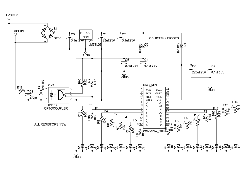
The DCC signal is an alternating voltage (AC) usually 16V, depending on your DCC controller. We use rectifier and LM7805 regulator to convert it to 5V (DC) that can safely power Arduino DCC decoder.

The 6N137 is a fast opto-coupler that is necessary because DCC decoding relies on measuring pulse width where 50µs represents 1 and 100µs represents 0. A slow opto-coupler could distort this timing.

The output of the opto-coupler is connected to Arduino pin 2. This pin provides the hardware interrupt mechanism that is used bye Arduino DCC data decoding library. Do not change this pin or your DCC decoder will not work.


Software
The software for a DCC decoder is remarkably simple thanks to NmraDcc DCC library. NmraDcc library can be downloaded here. Unzip it and move it to your Arduino libraries folder, usually found in My Documents/Arduino/libraries.

You will need to edit #define This_Decoder_Address 6 as this sets DCC address of Arduino DCC decoder to an address of your choice.

The following arduino sketch toggles 17 LEDs attached to the Arduino Pro Mini by pressing 6 (DCC address) on DCC controller, followed by function button and number that will toggle each LED independently.


#include <NmraDcc.h>
#include <SoftwareSerial.h>
byte rxPin = 0;
byte txPin = 1;
SoftwareSerial mySerial = SoftwareSerial(rxPin, txPin);
#define numleds 17
byte ledpins [] = {0,3,4,5,6,7,8,9,10,11,12,13,14,15,16,17,18,19};
const int FunctionPin0 = 3;
const int FunctionPin1 = 4; //D4
const int FunctionPin2 = 5; //D5
const int FunctionPin3 = 6; //D6
const int FunctionPin4 = 7; //D7
const int FunctionPin5 = 8; //D8
const int FunctionPin6 = 9; //D9
const int FunctionPin7 = 10; //D10
const int FunctionPin8 = 11; //D11
const int FunctionPin9 = 12;
const int FunctionPin10 = 13; //D3
const int FunctionPin11 = 14; //A0
const int FunctionPin12 = 15; //A1
const int FunctionPin13 = 16; //A2
const int FunctionPin14 = 17; //A3
const int FunctionPin15 = 18; //A4
const int FunctionPin16 = 19; //A5
NmraDcc Dcc;
DCC_MSG Packet;

#define This_Decoder_Address 6

extern uint8_t Decoder_Address = This_Decoder_Address;
struct CVPair {uint16_t CV; uint8_t Value; };
CVPair FactoryDefaultCVs [] = {{CV_MULTIFUNCTION_PRIMARY_ADDRESS, This_Decoder_Address}, {CV_ACCESSORY_DECODER_ADDRESS_MSB, 0}, {CV_MULTIFUNCTION_EXTENDED_ADDRESS_MSB, 0}, {CV_MULTIFUNCTION_EXTENDED_ADDRESS_LSB, 0},};

uint8_t FactoryDefaultCVIndex = 0;
void notifyCVResetFactoryDefault(){ FactoryDefaultCVIndex = sizeof(FactoryDefaultCVs)/sizeof(CVPair); };
void setup(){
pinMode(rxPin, INPUT);
pinMode(txPin, OUTPUT);
// initialize the digital pins as an outputs
for (int i=1; i<= numleds; i++){ pinMode(ledpins[i],OUTPUT); digitalWrite(ledpins[i],LOW); }
delay(500);
Dcc.pin(0, 2, 0); // Setup External Interrupt and enable the Pull-Up
Dcc.init( MAN_ID_DIY, 100, FLAGS_MY_ADDRESS_ONLY, 0 ); // Enable DCC Receiver
}
void loop(){
Dcc.process();
if( FactoryDefaultCVIndex && Dcc.isSetCVReady()){
FactoryDefaultCVIndex--; // Decrement first as initially it is the size of the array
Dcc.setCV( FactoryDefaultCVs[FactoryDefaultCVIndex].CV, FactoryDefaultCVs[FactoryDefaultCVIndex].Value);
}
}
extern void notifyDccFunc( uint16_t Addr, uint8_t FuncNum, uint8_t FuncState) {
if (FuncNum==1) { //Function Group 1 F0 F4 F3 F2 F1
digitalWrite( FunctionPin0, (FuncState&0x10)>>4 );
digitalWrite( FunctionPin1, (FuncState&0x01 ));
digitalWrite( FunctionPin2, (FuncState&0x02)>>1 );
digitalWrite( FunctionPin3, (FuncState&0x04)>>2 );
digitalWrite( FunctionPin4, (FuncState&0x08)>>3 );
}
else if (FuncNum==2) { //Function Group 1 S FFFF == 1 F8 F7 F6 F5 & == 0 F12 F11 F10 F9 F8
if ((FuncState & 0x10)==0x10) {
digitalWrite( FunctionPin5, (FuncState&0x01 ));
digitalWrite( FunctionPin6, (FuncState&0x02)>>1 );
digitalWrite( FunctionPin7, (FuncState&0x04)>>2 );
digitalWrite( FunctionPin8, (FuncState&0x08)>>3 );
}
else {
digitalWrite( FunctionPin9, (FuncState&0x01 ));
digitalWrite( FunctionPin10, (FuncState&0x02)>>1 );
digitalWrite( FunctionPin11, (FuncState&0x04)>>2 );
digitalWrite( FunctionPin12, (FuncState&0x08)>>3 );
}
}
else if (FuncNum==3) { //Function Group 2 FuncState == F20-F13 Function Control
digitalWrite( FunctionPin13, (FuncState&0x01 ));
digitalWrite( FunctionPin14, (FuncState&0x02)>>1 );
digitalWrite( FunctionPin15, (FuncState&0x04)>>2 );
digitalWrite( FunctionPin16, (FuncState&0x08)>>3 );
}
}


Notes
- 1N4148 small signal diode may be used in place of 1N4152 diode
- Two 1N5819 diodes are not critical and may be omitted
- R17 5K resistor may be replaced by 10K resistor
- C8 270pF capacitor is not critical and may be omitted
- Use 1K resistors in place of 10K for powering LEDs

DCC decoder test circuit with 8 LEDs. Arduino Pro Mini powered by external 5V DC power source omitting DC regulator circuitry.


Accurate LC Meter Capacitance Inductance Meter with 16F628 and LCD
Volt Ampere Meter with 16F876 Microcontroller and LCD display
 
Accurate LC Meter

Build your own Accurate LC Meter (Capacitance Inductance Meter) and start making your own coils and inductors. This LC Meter allows to measure incredibly small inductances making it perfect tool for making all types of RF coils and inductors. LC Meter can measure inductances starting from 10nH - 1000nH, 1uH - 1000uH, 1mH - 100mH and capacitances from 0.1pF up to 900nF. The circuit includes an auto ranging as well as reset switch and produces very accurate and stable readings.
PIC Volt Ampere Meter

Volt Ampere Meter measures voltage of 0-70V or 0-500V with 100mV resolution and current consumption 0-10A or more with 10mA resolution. The meter is a perfect addition to any power supply, battery chargers and other electronic projects where voltage and current must be monitored. The meter uses PIC16F876A microcontroller with 16x2 backlighted LCD.

50MHz 60MHz Frequency Meter / Counter with 16F628 & LCD
1Hz - 2MHz XR2206 Function Generator
60MHz Frequency Meter / Counter

Frequency Meter / Counter measures frequency from 10Hz to 60MHz with 10Hz resolution. It is a very useful bench test equipment for testing and finding out the frequency of various devices with unknown frequency such as oscillators, radio receivers, transmitters, function generators, crystals, etc.
1Hz - 2MHz XR2206 Function Generator

1Hz - 2MHz XR2206 Function Generator produces high quality sine, square and triangle waveforms of high-stability and accuracy. The output waveforms can be both amplitude and frequency modulated. Output of 1Hz - 2MHz XR2206 Function Generator can be connected directly to 60MHz Counter for setting precise frequency output.

BA1404 HI-FI Stereo FM Transmitter
USB IO Board PIC18F2455 / PIC18F2550
BA1404 HI-FI Stereo FM Transmitter

Be "On Air" with your own radio station! BA1404 HI-FI Stereo FM Transmitter broadcasts high quality stereo signal in 88MHz - 108MHz FM band. It can be connected to any type of stereo audio source such as iPod, Computer, Laptop, CD Player, Walkman, Television, Satellite Receiver, Tape Deck or other stereo system to transmit stereo sound with excellent clarity throughout your home, office, yard or camp ground.
USB IO Board

USB IO Board is a tiny spectacular little development board / parallel port replacement featuring PIC18F2455/PIC18F2550 microcontroller. USB IO Board is compatible with Windows / Mac OSX / Linux computers. When attached to Windows IO board will show up as RS232 COM port. You can control 16 individual microcontroller I/O pins by sending simple serial commands. USB IO Board is self-powered by USB port and can provide up to 500mA for electronic projects. USB IO Board is breadboard compatible.

ESR Meter / Transistor Tester Kit
Audiophile Headphone Amplifier Kit
 
ESR Meter / Capacitance / Inductance / Transistor Tester Kit

ESR Meter kit is an amazing multimeter that measures ESR values, capacitance (100pF - 20,000uF), inductance, resistance (0.1 Ohm - 20 MOhm), tests many different types of transistors such as NPN, PNP, FETs, MOSFETs, Thyristors, SCRs, Triacs and many types of diodes. It also analyzes transistor's characteristics such as voltage and gain. It is an irreplaceable tool for troubleshooting and repairing electronic equipment by determining performance and health of electrolytic capacitors. Unlike other ESR Meters that only measure ESR value this one measures capacitor's ESR value as well as its capacitance all at the same time.
Audiophile Headphone Amplifier Kit

Audiophile headphone amplifier kit includes high quality audio grade components such as Burr Brown OPA2134 opamp, ALPS volume control potentiometer, Ti TLE2426 rail splitter, Ultra-Low ESR 220uF/25V Panasonic FM filtering capacitors, High quality WIMA input and decoupling capacitors and Vishay Dale resistors. 8-DIP machined IC socket allows to swap OPA2134 with many other dual opamp chips such as OPA2132, OPA2227, OPA2228, dual OPA132, OPA627, etc. Headphone amplifier is small enough to fit in Altoids tin box, and thanks to low power consumption may be supplied from a single 9V battery.
 

Arduino Prototype Kit
RF Remote Control 433MHz Four Channel
 
Arduino Prototype Kit

Arduino Prototype is a spectacular development board fully compatible with Arduino Pro. It's breadboard compatible so it can be plugged into a breadboard for quick prototyping, and it has VCC & GND power pins available on both sides of PCB. It's small, power efficient, yet customizable through onboard 2 x 7 perfboard that can be used for connecting various sensors and connectors. Arduino Prototype uses all standard through-hole components for easy construction, two of which are hidden underneath IC socket. Board features 28-PIN DIP IC socket, user replaceable ATmega328 microcontroller flashed with Arduino bootloader, 16MHz crystal resonator and a reset switch. It has 14 digital input/output pins (0-13) of which 6 can be used as PWM outputs and 6 analog inputs (A0-A5). Arduino sketches are uploaded through any USB-Serial adapter connected to 6-PIN ICSP female header. Board is supplied by 2-5V voltage and may be powered by a battery such as Lithium Ion cell, two AA cells, external power supply or USB power adapter.
200m 4-Channel 433MHz Wireless RF Remote Control

Having the ability to control various appliances inside or outside of your house wirelessly is a huge convenience, and can make your life much easier and fun. RF remote control provides long range of up to 200m / 650ft and can find many uses for controlling different devices, and it works even through the walls. You can control lights, fans, AC system, computer, printer, amplifier, robots, garage door, security systems, motor-driven curtains, motorized window blinds, door locks, sprinklers, motorized projection screens and anything else you can think of.
 

Electronics-DIY.com © 2002-2024. All Rights Reserved.