HOME     STORE     BLOG     SCHEMATICS     TUTORIALS     DOWNLOADS     CONTACT

Arduino RF link using 433MHz Transmitter / Receiver modules
 
Arduino RF link using 433MHz Transmitter / Receiver modules


Arduino RF link using 433MHz Transmitter / Receiver modules


If you are looking into wireless communication between two Arduino modules, this project might be helpful. It uses low costs RF transmitter and receiver from Electronics-DIY.com to establish radio link between two Arduino boards up to 500 ft. Data can be transferred serially at the maximum rate of 2400 bps. The schematic shows how receiver and transmitter is hooked up to two different Arduino boards. When wiring the receiver / transmitter you only need to give them power / ground and then a pin for the TX (serial transmit) or RX (serial receive) pin. I also wired a button to the Arduino doing the transmitting, and used the LED on pin 13 that is built into my Arduino boards on the receiver so I could test this setup. The test app just flashes LED on the receiving board when a button is pressed on the transmitting board.


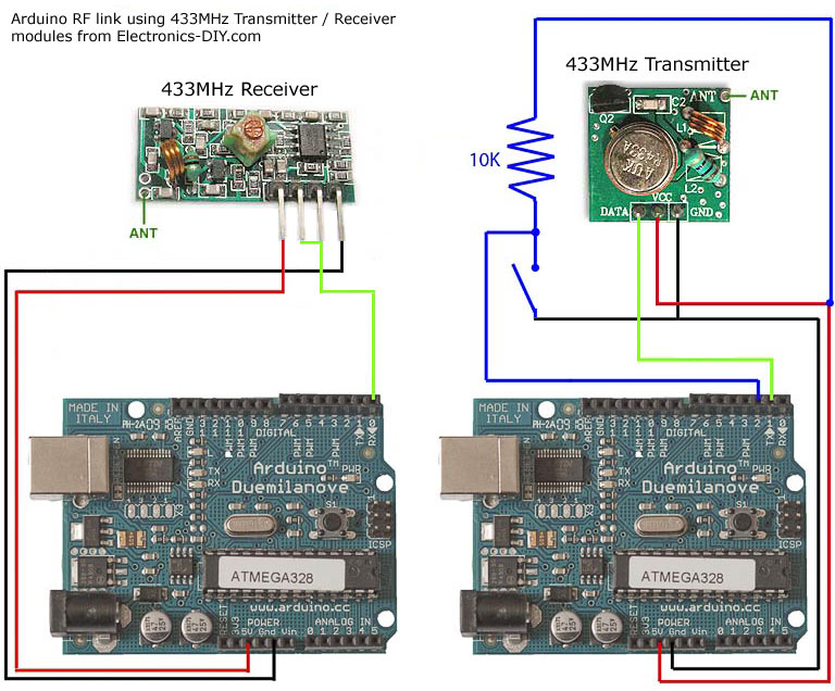
I was looking for a way to handle wireless communications between two Arduino boards. Then I found inexpensive RF transmitter and receiver modules at Electronics-DIY.com.

Here are some things to consider while using RF solution:

- Communications is only one way. If you wanted two way communications you’d need to buy two receivers and two transmitters.

- The variable gain on the receiver causes it to pick up lots of background noise. I had to do some processing with the Arduino to filter out this noise. More details about this below in the code section.

- Bandwidth maxes out at 2400 bps, but there is a version with 4800 bps. A large portion of this bandwidth is used for network protocol I wrote that handles error detection.

- Range is limited to a max of 500 feet.

The advantages are that it is cheap and it is pretty easy to use.


Code

Since the receiver is constantly picking up random noise I add a few extra bytes to every data packet. I add two bytes to signify the start of a data packet. Then I send the a byte address. This address allows multiple devices to work in the same area without interfering with each other. Next is the data (in my example code it’s an unsigned int (2 bytes). Lastly I send a checksum which is a simple xor of all the data bytes to make sure the data got received without being corrupted.

I broke the Arduino code into two files. If you’ve never used two files before with Arduino all you need to to is keep both files in the same directory and the Arduino IDE merges them for you.

Here is the full code for the main application


// Used Arduino 0017
// This is a simple test app for cheap RF transmitter and receiver hardware.
// 433MHz RF Transmitter: http://electronics-diy.com/product_details.php?pid=250
// 433MHz RF Receiver: http://electronics-diy.com/product_details.php?pid=251

// This says whether you are building the transmistor or reciever.
// Only one of these should be defined.
//#define TRANSMITTER
#define RECEIVER

// Arduino digital pins
#define BUTTON_PIN 2
#define LED_PIN 13

// Button hardware is setup so the button goes LOW when pressed
#define BUTTON_PRESSED LOW
#define BUTTON_NOT_PRESSED HIGH

void setup()
{
pinMode(BUTTON_PIN, INPUT);
pinMode(LED_PIN, OUTPUT);
digitalWrite(LED_PIN, LOW);

Serial.begin(1200); // Hardware supports up to 2400, but 1200 gives longer range
}

#ifdef TRANSMITTER
void loop()
{
static int prev_button = BUTTON_NOT_PRESSED; // Previous button press value
int cur_button; // Current button press value

cur_button = digitalRead(BUTTON_PIN);

if ((prev_button == BUTTON_NOT_PRESSED) && (cur_button == BUTTON_PRESSED))
{
writeUInt(271); // Put any number you want to send here (71 is just a test)
}

delay(50); // Debounce button
prev_button = cur_button;
}
#endif //TRANSMITTER

#ifdef RECEIVER
void loop()
{
boolean light_led = false;

if (readUInt(true) == 271) // Check to see if we got the 71 test number
{
light_led = true;
}

if (light_led)
{
digitalWrite(LED_PIN, HIGH);
delay(1000);
digitalWrite(LED_PIN, LOW);
}
}
#endif //RECEIVER


Full code that does the network error catching


// Used Arduino 0017
// This does does some error checking to try to make sure the receiver on this one way RF serial link doesn't repond to garbage

#define NETWORK_SIG_SIZE 3

#define VAL_SIZE 2
#define CHECKSUM_SIZE 1
#define PACKET_SIZE (NETWORK_SIG_SIZE + VAL_SIZE + CHECKSUM_SIZE)

// The network address byte and can be change if you want to run different devices in proximity to each other without interfearance
#define NET_ADDR 5

const byte g_network_sig[NETWORK_SIG_SIZE] = {0x8F, 0xAA, NET_ADDR}; // Few bytes used to initiate a transfer

// Sends an unsigned int over the RF network
void writeUInt(unsigned int val)
{
byte checksum = (val/256) ^ (val&0xFF);
Serial.write(0xF0); // This gets reciever in sync with transmitter
Serial.write(g_network_sig, NETWORK_SIG_SIZE);
Serial.write((byte*)&val, VAL_SIZE);
Serial.write(checksum); //CHECKSUM_SIZE
}

// Receives an unsigned int over the RF network
unsigned int readUInt(bool wait)
{
int pos = 0; // Position in the network signature
unsigned int val; // Value of the unsigned int
byte c = 0; // Current byte

if((Serial.available() < PACKET_SIZE) && (wait == false))
{
return 0xFFFF;
}

while(pos < NETWORK_SIG_SIZE)
{
while(Serial.available() == 0); // Wait until something is avalible
c = Serial.read();

if (c == g_network_sig[pos])
{
if (pos == NETWORK_SIG_SIZE-1)
{
byte checksum;

while(Serial.available() < VAL_SIZE + CHECKSUM_SIZE); // Wait until something is avalible
val = Serial.read();
val += ((unsigned int)Serial.read())*256;
checksum = Serial.read();

if (checksum != ((val/256) ^ (val&0xFF)))
{
// Checksum failed
pos = -1;
}
}
++pos;
}
else if (c == g_network_sig[0])
{
pos = 1;
}
else
{
pos = 0;
if (!wait)
{
return 0xFFFF;
}
}
}
return val;
}


Increasing the Range

I did all of my initial testing without any of these improvement and everything worked fine with these devices inside the same room.

- Add an antenna. All you need is a 23 cm piece of wire. I did this and it made it so I could reliably transmit data from one corner of my house to the other (3 floor town house).

- Increase the voltage for the transmitter. The transmitter can use 2-12 volts. With 5 volts I got pleanty of range for my use case, but increase this if you need more range.

- Reduce the baud rate. My test app runs at 1200 bps out of the max 2400 bps. You could drop this even further to something like 300 bps and that should help reduce transfer errors and hopefully increase range.


Accurate LC Meter Capacitance Inductance Meter with 16F628 and LCD
Volt Ampere Meter with 16F876 Microcontroller and LCD display
 
Accurate LC Meter

Build your own Accurate LC Meter (Capacitance Inductance Meter) and start making your own coils and inductors. This LC Meter allows to measure incredibly small inductances making it perfect tool for making all types of RF coils and inductors. LC Meter can measure inductances starting from 10nH - 1000nH, 1uH - 1000uH, 1mH - 100mH and capacitances from 0.1pF up to 900nF. The circuit includes an auto ranging as well as reset switch and produces very accurate and stable readings.
PIC Volt Ampere Meter

Volt Ampere Meter measures voltage of 0-70V or 0-500V with 100mV resolution and current consumption 0-10A or more with 10mA resolution. The meter is a perfect addition to any power supply, battery chargers and other electronic projects where voltage and current must be monitored. The meter uses PIC16F876A microcontroller with 16x2 backlighted LCD.

50MHz 60MHz Frequency Meter / Counter with 16F628 & LCD
1Hz - 2MHz XR2206 Function Generator
60MHz Frequency Meter / Counter

Frequency Meter / Counter measures frequency from 10Hz to 60MHz with 10Hz resolution. It is a very useful bench test equipment for testing and finding out the frequency of various devices with unknown frequency such as oscillators, radio receivers, transmitters, function generators, crystals, etc.
1Hz - 2MHz XR2206 Function Generator

1Hz - 2MHz XR2206 Function Generator produces high quality sine, square and triangle waveforms of high-stability and accuracy. The output waveforms can be both amplitude and frequency modulated. Output of 1Hz - 2MHz XR2206 Function Generator can be connected directly to 60MHz Counter for setting precise frequency output.

BA1404 HI-FI Stereo FM Transmitter
USB IO Board PIC18F2455 / PIC18F2550
BA1404 HI-FI Stereo FM Transmitter

Be "On Air" with your own radio station! BA1404 HI-FI Stereo FM Transmitter broadcasts high quality stereo signal in 88MHz - 108MHz FM band. It can be connected to any type of stereo audio source such as iPod, Computer, Laptop, CD Player, Walkman, Television, Satellite Receiver, Tape Deck or other stereo system to transmit stereo sound with excellent clarity throughout your home, office, yard or camp ground.
USB IO Board

USB IO Board is a tiny spectacular little development board / parallel port replacement featuring PIC18F2455/PIC18F2550 microcontroller. USB IO Board is compatible with Windows / Mac OSX / Linux computers. When attached to Windows IO board will show up as RS232 COM port. You can control 16 individual microcontroller I/O pins by sending simple serial commands. USB IO Board is self-powered by USB port and can provide up to 500mA for electronic projects. USB IO Board is breadboard compatible.

ESR Meter / Transistor Tester Kit
Audiophile Headphone Amplifier Kit
 
ESR Meter / Capacitance / Inductance / Transistor Tester Kit

ESR Meter kit is an amazing multimeter that measures ESR values, capacitance (100pF - 20,000uF), inductance, resistance (0.1 Ohm - 20 MOhm), tests many different types of transistors such as NPN, PNP, FETs, MOSFETs, Thyristors, SCRs, Triacs and many types of diodes. It also analyzes transistor's characteristics such as voltage and gain. It is an irreplaceable tool for troubleshooting and repairing electronic equipment by determining performance and health of electrolytic capacitors. Unlike other ESR Meters that only measure ESR value this one measures capacitor's ESR value as well as its capacitance all at the same time.
Audiophile Headphone Amplifier Kit

Audiophile headphone amplifier kit includes high quality audio grade components such as Burr Brown OPA2134 opamp, ALPS volume control potentiometer, Ti TLE2426 rail splitter, Ultra-Low ESR 220uF/25V Panasonic FM filtering capacitors, High quality WIMA input and decoupling capacitors and Vishay Dale resistors. 8-DIP machined IC socket allows to swap OPA2134 with many other dual opamp chips such as OPA2132, OPA2227, OPA2228, dual OPA132, OPA627, etc. Headphone amplifier is small enough to fit in Altoids tin box, and thanks to low power consumption may be supplied from a single 9V battery.
 

Arduino Prototype Kit
RF Remote Control 433MHz Four Channel
 
Arduino Prototype Kit

Arduino Prototype is a spectacular development board fully compatible with Arduino Pro. It's breadboard compatible so it can be plugged into a breadboard for quick prototyping, and it has VCC & GND power pins available on both sides of PCB. It's small, power efficient, yet customizable through onboard 2 x 7 perfboard that can be used for connecting various sensors and connectors. Arduino Prototype uses all standard through-hole components for easy construction, two of which are hidden underneath IC socket. Board features 28-PIN DIP IC socket, user replaceable ATmega328 microcontroller flashed with Arduino bootloader, 16MHz crystal resonator and a reset switch. It has 14 digital input/output pins (0-13) of which 6 can be used as PWM outputs and 6 analog inputs (A0-A5). Arduino sketches are uploaded through any USB-Serial adapter connected to 6-PIN ICSP female header. Board is supplied by 2-5V voltage and may be powered by a battery such as Lithium Ion cell, two AA cells, external power supply or USB power adapter.
200m 4-Channel 433MHz Wireless RF Remote Control

Having the ability to control various appliances inside or outside of your house wirelessly is a huge convenience, and can make your life much easier and fun. RF remote control provides long range of up to 200m / 650ft and can find many uses for controlling different devices, and it works even through the walls. You can control lights, fans, AC system, computer, printer, amplifier, robots, garage door, security systems, motor-driven curtains, motorized window blinds, door locks, sprinklers, motorized projection screens and anything else you can think of.
 

Electronics-DIY.com © 2002-2024. All Rights Reserved.