| |
Arduino Sinewave Generator |
|
Arduino Sine wave Generator using the direct digital synthesis Method.
Here we describe how to generate sine waves with an Arduino board in a very accurate way. Almost no additional hardware is required. The frequency range reaches form zero to 16 KHz with a resolution of a millionth part of one Hertz! Distortions can be kept less than one percent on frequencies up to 3 KHz. This technique is not only useful for music and sound generation another range of application is test equipment or measurement instrumentation. Also in telecommunication the DDS Method is useful for instance in frequency of phase modulation (FSK PSK).
The DDS Method (digital direct synthesis).
To implement the DDS Method in software we need four components. An accumulator and a tuning word which are in our case just two long integer variables, a sinewave table as a list of numerical values of one sine period stored as constants, a digital analog converter which is provided by the PWM (analogWrite) unit, and a reference clock derived by a internal hardware timer in the atmega. To the accumulator , the tuning word is added, the most significant byte of the accu is taken as address of the sinetable where the value is fetched and outputted as analog value bye the PWM unit. The whole process is cycle timed by an interrupt process which acts as the reference clock. Further details of the DDS Method are described in web of course.

Software implementation
To run this software on an Arduino Diecimila or Duemilenove connect a potentiometer to +5Volt and Ground and the wiper to analog 0. The frequency appears on pin 11 where you can connect active speakers or an output filter described later.
/*
*
* DDS Sine Generator mit ATMEGS 168
* Timer2 generates the 31250 KHz Clock Interrupt
*
* KHM 2009 / Martin Nawrath
* Kunsthochschule fuer Medien Koeln
* Academy of Media Arts Cologne
*/
#include "avr/pgmspace.h"
// table of 256 sine values / one sine period / stored in flash memory
PROGMEM prog_uchar sine256[] = {
127,130,133,136,139,143,146,149,152,155,158,161,164,167,170,173,176,178,181,184,187,190,192,195,198,200,203,205,208,210,212,215,217,219,221,223,225,227,229,231,233,234,236,238,239,240,
242,243,244,245,247,248,249,249,250,251,252,252,253,253,253,254,254,254,254,254,254,254,253,253,253,252,252,251,250,249,249,248,247,245,244,243,242,240,239,238,236,234,233,231,229,227,225,223,
221,219,217,215,212,210,208,205,203,200,198,195,192,190,187,184,181,178,176,173,170,167,164,161,158,155,152,149,146,143,139,136,133,130,127,124,121,118,115,111,108,105,102,99,96,93,90,87,84,81,78,
76,73,70,67,64,62,59,56,54,51,49,46,44,42,39,37,35,33,31,29,27,25,23,21,20,18,16,15,14,12,11,10,9,7,6,5,5,4,3,2,2,1,1,1,0,0,0,0,0,0,0,1,1,1,2,2,3,4,5,5,6,7,9,10,11,12,14,15,16,18,20,21,23,25,27,29,31,
33,35,37,39,42,44,46,49,51,54,56,59,62,64,67,70,73,76,78,81,84,87,90,93,96,99,102,105,108,111,115,118,121,124
};
#define cbi(sfr, bit) (_SFR_BYTE(sfr) &= ~_BV(bit))
#define sbi(sfr, bit) (_SFR_BYTE(sfr) |= _BV(bit))
int ledPin = 13; // LED pin 7
int testPin = 7;
int t2Pin = 6;
byte bb;
double dfreq;
// const double refclk=31372.549; // =16MHz / 510
const double refclk=31376.6; // measured
// variables used inside interrupt service declared as voilatile
volatile byte icnt; // var inside interrupt
volatile byte icnt1; // var inside interrupt
volatile byte c4ms; // counter incremented all 4ms
volatile unsigned long phaccu; // pahse accumulator
volatile unsigned long tword_m; // dds tuning word m
void setup()
{
pinMode(ledPin, OUTPUT); // sets the digital pin as output
Serial.begin(115200); // connect to the serial port
Serial.println("DDS Test");
pinMode(6, OUTPUT); // sets the digital pin as output
pinMode(7, OUTPUT); // sets the digital pin as output
pinMode(11, OUTPUT); // pin11= PWM output / frequency output
Setup_timer2();
// disable interrupts to avoid timing distortion
cbi (TIMSK0,TOIE0); // disable Timer0 !!! delay() is now not available
sbi (TIMSK2,TOIE2); // enable Timer2 Interrupt
dfreq=1000.0; // initial output frequency = 1000.o Hz
tword_m=pow(2,32)*dfreq/refclk; // calulate DDS new tuning word
}
void loop()
{
while(1) {
if (c4ms > 250) { // timer / wait fou a full second
c4ms=0;
dfreq=analogRead(0); // read Poti on analog pin 0 to adjust output frequency from 0..1023 Hz
cbi (TIMSK2,TOIE2); // disble Timer2 Interrupt
tword_m=pow(2,32)*dfreq/refclk; // calulate DDS new tuning word
sbi (TIMSK2,TOIE2); // enable Timer2 Interrupt
Serial.print(dfreq);
Serial.print(" ");
Serial.println(tword_m);
}
sbi(PORTD,6); // Test / set PORTD,7 high to observe timing with a scope
cbi(PORTD,6); // Test /reset PORTD,7 high to observe timing with a scope
}
}
//******************************************************************
// timer2 setup
// set prscaler to 1, PWM mode to phase correct PWM, 16000000/510 = 31372.55 Hz clock
void Setup_timer2() {
// Timer2 Clock Prescaler to : 1
sbi (TCCR2B, CS20);
cbi (TCCR2B, CS21);
cbi (TCCR2B, CS22);
// Timer2 PWM Mode set to Phase Correct PWM
cbi (TCCR2A, COM2A0); // clear Compare Match
sbi (TCCR2A, COM2A1);
sbi (TCCR2A, WGM20); // Mode 1 / Phase Correct PWM
cbi (TCCR2A, WGM21);
cbi (TCCR2B, WGM22);
}
//******************************************************************
// Timer2 Interrupt Service at 31372,550 KHz = 32uSec
// this is the timebase REFCLOCK for the DDS generator
// FOUT = (M (REFCLK)) / (2 exp 32)
// runtime : 8 microseconds ( inclusive push and pop)
ISR(TIMER2_OVF_vect) {
sbi(PORTD,7); // Test / set PORTD,7 high to observe timing with a oscope
phaccu=phaccu+tword_m; // soft DDS, phase accu with 32 bits
icnt=phaccu >> 24; // use upper 8 bits for phase accu as frequency information
// read value fron ROM sine table and send to PWM DAC
OCR2A=pgm_read_byte_near(sine256 + icnt);
if(icnt1++ == 125) { // increment variable c4ms all 4 milliseconds
c4ms++;
icnt1=0;
}
cbi(PORTD,7); // reset PORTD,7
}
Results
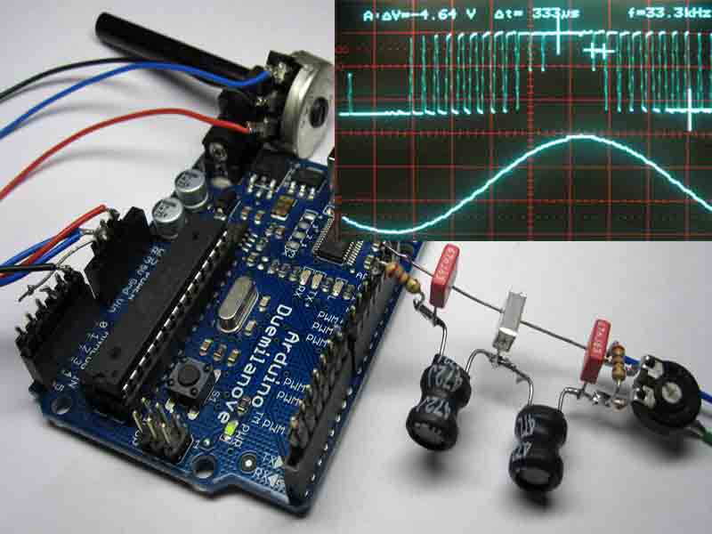
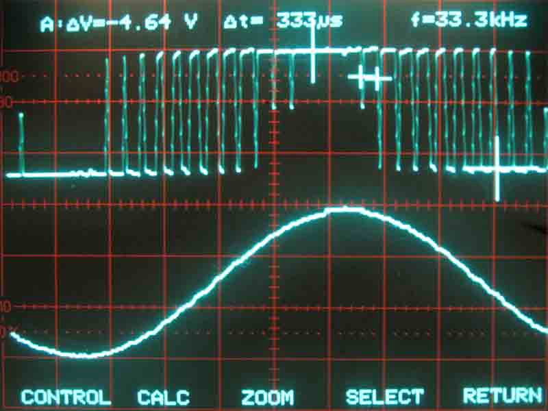
In the upper part of the picture you see PWM signal on pin 11 and in the lower part what the filter makes out of it. The sinewave looks not so clean but thats mainly the limited resolution of the digital oscilloscope.
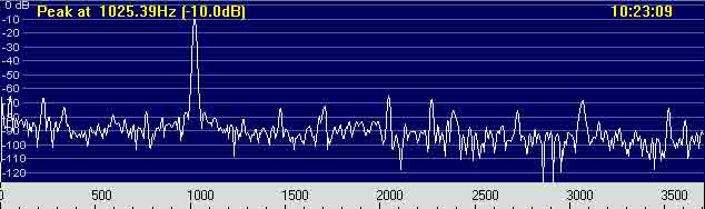
The spectrogram shows a surprisingly good result. The big peak is the output frequency of about 1000 Hz. All unwanted distortions are below 50 dB which is roughly what we expect from a signal what is generated by an 8-bit DAC. ( 1/256 = 48dB).
DDS Spreadsheet
dds_calc A little worksheet around the DDS formula to calculate the tuning word.
PWM Output lowpass Filter
For a start you can just connect the output pin 11 to active speakers. But usually you need lowpass filter is to get rid of the 32KHz sampling frequency in the output signal. A Chebyshef lowpass with a cutoff at 12 KHz build with standard component values is shown here.
PWM DDS dedicated Hardware
This software implementation of DDS has of course several drawbacks in case of signal purity and frequency range due to the limited speed of the software algorithm and analog capabilities of the atmega chip. DDS modules which are using dedicated DDS chips are the state of the art in signal generation and offer a frequency coverage from zero up into the 100MHz range.
WSPR Application
WSPR “Weak Signal Propagation Reporter” pronounced Whisper is a system which reports the propagation of very weak radio signals over the world. The DDS Method was used here to generate a tone sequence where four frequencies (1497,8 1499,3 1500,7 1502,2 Hz) are used code a message in a very robust manner. This message is transmitted with a low power radio beacon and can be observed worldwide via wspr.net .
Related Links
Downloads
Arduino Sinewave Generator - Link
|
|
|
| |
Accurate LC Meter
Build your own Accurate LC Meter (Capacitance Inductance Meter) and start making your own coils and inductors. This LC Meter allows to measure incredibly small inductances making it perfect tool for making all types of RF coils and inductors. LC Meter can measure inductances starting from 10nH - 1000nH, 1uH - 1000uH, 1mH - 100mH and capacitances from 0.1pF up to 900nF. The circuit includes an auto ranging as well as reset switch and produces very accurate and stable readings. |
|
PIC Volt Ampere Meter
Volt Ampere Meter measures voltage of 0-70V or 0-500V with 100mV resolution and current consumption 0-10A or more with 10mA resolution. The meter is a perfect addition to any power supply, battery chargers and other electronic projects where voltage and current must be monitored. The meter uses PIC16F876A microcontroller with 16x2 backlighted LCD. |
|
|
|
60MHz Frequency Meter / Counter
Frequency Meter / Counter measures frequency from 10Hz to 60MHz with 10Hz resolution. It is a very useful bench test equipment for testing and finding out the frequency of various devices with unknown frequency such as oscillators, radio receivers, transmitters, function generators, crystals, etc. |
|
1Hz - 2MHz XR2206 Function Generator
1Hz - 2MHz XR2206 Function Generator produces high quality sine, square and triangle waveforms of high-stability and accuracy. The output waveforms can be both amplitude and frequency modulated. Output of 1Hz - 2MHz XR2206 Function Generator can be connected directly to 60MHz Counter for setting precise frequency output. |
|
|
|
BA1404 HI-FI Stereo FM Transmitter
Be "On Air" with your own radio station! BA1404 HI-FI Stereo FM Transmitter broadcasts high quality stereo signal in 88MHz - 108MHz FM band. It can be connected to any type of stereo audio source such as iPod, Computer, Laptop, CD Player, Walkman, Television, Satellite Receiver, Tape Deck or other stereo system to transmit stereo sound with excellent clarity throughout your home, office, yard or camp ground. |
|
USB IO Board
USB IO Board is a tiny spectacular little development board / parallel port replacement featuring PIC18F2455/PIC18F2550 microcontroller. USB IO Board is compatible with Windows / Mac OSX / Linux computers. When attached to Windows IO board will show up as RS232 COM port. You can control 16 individual microcontroller I/O pins by sending simple serial commands. USB IO Board is self-powered by USB port and can provide up to 500mA for electronic projects. USB IO Board is breadboard compatible. |
|
|
|
|
ESR Meter / Capacitance / Inductance / Transistor Tester Kit
ESR Meter kit is an amazing multimeter that measures ESR values, capacitance (100pF - 20,000uF), inductance, resistance (0.1 Ohm - 20 MOhm), tests many different types of transistors such as NPN, PNP, FETs, MOSFETs, Thyristors, SCRs, Triacs and many types of diodes. It also analyzes transistor's characteristics such as voltage and gain. It is an irreplaceable tool for troubleshooting and repairing electronic equipment by determining performance and health of electrolytic capacitors. Unlike other ESR Meters that only measure ESR value this one measures capacitor's ESR value as well as its capacitance all at the same time. |
|
Audiophile Headphone Amplifier Kit
Audiophile headphone amplifier kit includes high quality audio grade components such as Burr Brown OPA2134 opamp, ALPS volume control potentiometer, Ti TLE2426 rail splitter, Ultra-Low ESR 220uF/25V Panasonic FM filtering capacitors, High quality WIMA input and decoupling capacitors and Vishay Dale resistors. 8-DIP machined IC socket allows to swap OPA2134 with many other dual opamp chips such as OPA2132, OPA2227, OPA2228, dual OPA132, OPA627, etc. Headphone amplifier is small enough to fit in Altoids tin box, and thanks to low power consumption may be supplied from a single 9V battery. |
|
|
|
|
|
Arduino Prototype Kit
Arduino Prototype is a spectacular development board fully compatible with Arduino Pro. It's breadboard compatible so it can be plugged into a breadboard for quick prototyping, and it has VCC & GND power pins available on both sides of PCB. It's small, power efficient, yet customizable through onboard 2 x 7 perfboard that can be used for connecting various sensors and connectors. Arduino Prototype uses all standard through-hole components for easy construction, two of which are hidden underneath IC socket. Board features 28-PIN DIP IC socket, user replaceable ATmega328 microcontroller flashed with Arduino bootloader, 16MHz crystal resonator and a reset switch. It has 14 digital input/output pins (0-13) of which 6 can be used as PWM outputs and 6 analog inputs (A0-A5). Arduino sketches are uploaded through any USB-Serial adapter connected to 6-PIN ICSP female header. Board is supplied by 2-5V voltage and may be powered by a battery such as Lithium Ion cell, two AA cells, external power supply or USB power adapter. |
|
200m 4-Channel 433MHz Wireless RF Remote Control
Having the ability to control various appliances inside or outside of your house wirelessly is a huge convenience, and can make your life much easier and fun. RF remote control provides long range of up to 200m / 650ft and can find many uses for controlling different devices, and it works even through the walls. You can control lights, fans, AC system, computer, printer, amplifier, robots, garage door, security systems, motor-driven curtains, motorized window blinds, door locks, sprinklers, motorized projection screens and anything else you can think of. |
|
|
|