| |
Building Simple FM Transmitter |
|
This article shows you how to build a very simple FM transmitter from thirteen components, a Printed Circuit Board (PCB) and a 9v battery.
This project was designed to be mounted on a PCB, however you don’t have to. You could construct the project on Vero board (strip board) or any other 0.1” pitch style of project board. If you just want to experiment with this circuit, you don’t even need a board; you can just solder the component s together and let the completed project just rest on the work top. No matter which style you choose, try to keep all component leads nice and short.
You could also make the PCB much smaller than the one shown here which is approx. 3 cm square. This is a good size to keep the unit small but nicer to work on for beginners. If you wanted to make one really small, you could use all SMT parts.
Selecting the operating frequency range
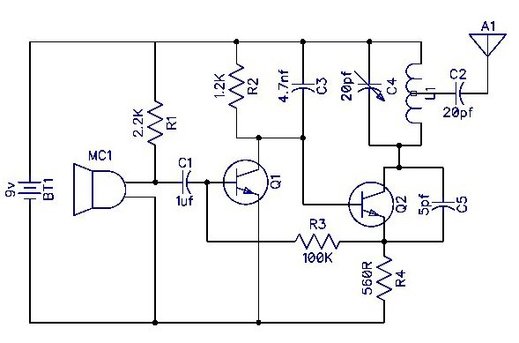
The value of capacitor C5 controls the transmission frequency range.
In the UK, domestic FM radio receivers cover from around 88 - 108MHz.
The following table shows an approximate frequency range that can be expected for different values of C5.
These are only approximate as frequency is determined by the L1 and the specification of the transistors, but these ranges were observed in the prototype unit. Also note that the closer the coil windings are, the lower the frequency will be. Just slightly compressing the coil dropped the transmission frequency by over 1 MHz.
C5 Value Lower Freq. Upper Freq.
5pf 130MHz 180MHz
10pf 115MHz 152MHz
22pf 106MHz 124MHz
47pf 89MHz 97MHz
100pf 73MHz 75MHz
Again this is just a rough guide. Different makes of capacitors will give different frequencies.
I personally picked a frequency that was outside of domestic FM receives so that I wouldn't bother anybody; and nobody else can "tune-in" by accident. However, if you don't have a communications receiver then you will have to pick a frequency range that you can receive with your FM radio equipment.
Winding the coil
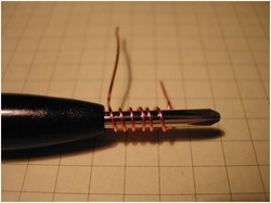
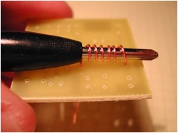
The first think to do is wind and mount the coil. The coil is simply a length of 0.6mm / 22swg copper wire wound into a coil. Take a 10cm length of bare copper wire and wind it around a suitable former; the blade of a jewellers screwdriver or knitting needle is ideal.
You will need between 4 to 6 turns and you may have to experiment here. 6 turns gave my prototype a transmission frequency of around 120MHz. A coil with fewer turns should reduce the frequency.
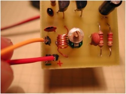
Mounting the coil on the board
Once the coil has been wound, leave it on the winding former for now so that it doesn’t get deformed whilst your mounting it. Pop each end of the coil into the correct PCB hole stretching the coil as needed so that its windings are evenly spaced. Turn over the PCB and solder in both ends of the coil.
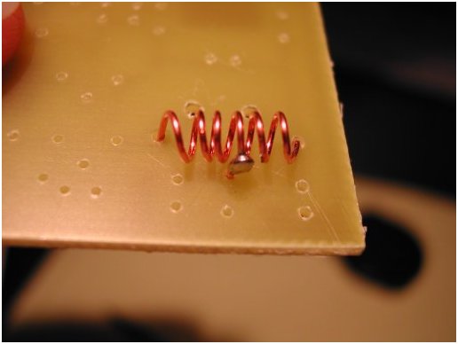
The above three images show how the coil centre-tap wire is made and then fixed to the coil.
Solder the centre-tap wire to the approximate centre position of the coil. When it’s secure, turn over the PCB and solder the wire to the track and trim off the excess wire.
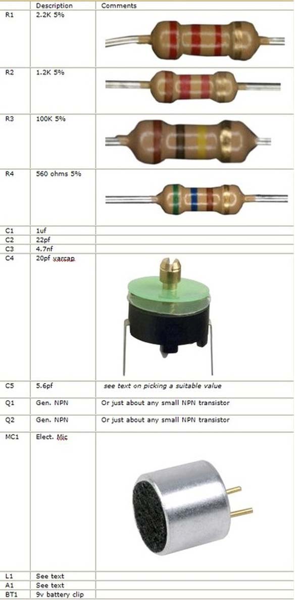
Solder the remaining components
Next mount the remaining components except the transistors, in any order that you feel most comfortable with.
Lastly, you need to mount the transistors Q1 & Q2, and you need to be VERY carful that you insert them the correct way. Depending on which transistors you use, you may have to bend some of the legs around each other. If you need to do this, make sure that they don’t touch each other.
Now solder in the wires from the 9 volt battery clip making sure you get the positive and negative the correct way around.
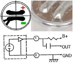
Connecting the microphone
When it comes time to solder on the microphone you need to be carfull. On the base of the mic there will be two solder pads. If you look closely, one of the pads should be connected to the case; this is the Negative.
If you connect the mic the wrong way around it won't work and you will probably damage it.
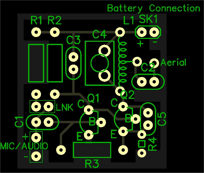
Notice above C1 in figure 6, there is a small link wire - LNK.
This allows power to be applied to the microphone via R1. If you decide to not use this type of mic or to connect the transmitter to another audio source, you should remove this link.
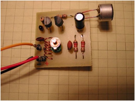
Completed FM transmitter
You don’t need anything clever in the way of aerials for this transmitter. The longer the aerial wire is, the further the transmission range will be but for testing, just connect a 25cm length.
Make sure that the other end of the aerial doesn’t come into contact with anything; that includes any part of the circuit or anything that may be earthed.
When you’re done, you should end up with something that looks like the picture on the left.
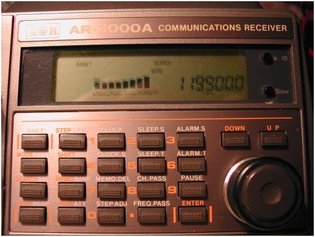
First tests FM receiver showing 119.9 MHz
Ok, now for the tricky bit. Assuming you’ve connected everything together correctly, then depending on the transistors used, tolerance of the components, characteristics of your coil and position of the trimmer capacitor, when you connect the battery you will be transmitting audio somewhere on the FM band, probably between 80MHz and 150MHz.
Place your FM transmitter near an FM radio and SLOWLY start to tune from one end of the band to the other. As you tune the radio with one hand, keep gently tapping the microphone on the transmitter with the other hand. At some point you should hopefully start to hear the tapping. When tuning you need to experiment to find the exact frequency. When you find the frequency, make a note of it and keep going a bit further. Sometimes you can find a stronger signal a little further down the dial.
Those using a communications receiver or scanner should select WFM or Wide FM if available.
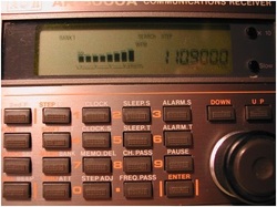
Changing the transmission frequency
Crushed coil to lower the frequency
With the component values specified, both my trial units popped up at around the same frequency.
I then “crushed” the coil slightly; almost certainly one or more of the turns are now shorting together (see fig.10) and this immediatly lowered the transmission frequency.
Frequency has dropped to around 110.9 MHz
When tuning the transmitter don't touch any part of the circuit as you will cause the output frequency to drift around.
Now the microphone used has a built in audio amplifier (see Figure 7) and I kid you not, it can hear an ant blowing its nose at 50 meters. If you just speak softly close up into the microphone it will probably sound distorted because you will over load the input.
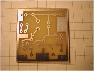
The PCB was designed using DipTrace PCB software and there is a free version of this product available for download that can be used to modify / print the foil. You will find the original PCB foil for download at the end of this article.
One question this is often asked is "what's the transmission range?".
The problem with attempting to answer this question is that it depends on so many external factors including, number and density of obstacles between the transmitter and receiver, sensitivity of the receiver, the quantity and strength of other transmissions on or around the chosen wavelength that can overload the receiver, and the size of transmitting and receiving aerials. As a rough guide, assuming that a clear part of the frequency spectrum can be located and a nice long aerial is connected to the receiver, I've had around 250 meters in the city or built up area with a one Meter wire aerial on the transmitter, but a fair bit more distance out in the open of it it's used up high.
Reducing the value of R4 will increase the drive to Q2 thus increasing the transmitter power output. However, if you reduce R4 too much you will shorten the life of the battery and may eventually destroy transistor Q2.
Related Links
Downloads
Building Simple FM Transmitter - Link
|
|
|
| |
Accurate LC Meter
Build your own Accurate LC Meter (Capacitance Inductance Meter) and start making your own coils and inductors. This LC Meter allows to measure incredibly small inductances making it perfect tool for making all types of RF coils and inductors. LC Meter can measure inductances starting from 10nH - 1000nH, 1uH - 1000uH, 1mH - 100mH and capacitances from 0.1pF up to 900nF. The circuit includes an auto ranging as well as reset switch and produces very accurate and stable readings. |
|
PIC Volt Ampere Meter
Volt Ampere Meter measures voltage of 0-70V or 0-500V with 100mV resolution and current consumption 0-10A or more with 10mA resolution. The meter is a perfect addition to any power supply, battery chargers and other electronic projects where voltage and current must be monitored. The meter uses PIC16F876A microcontroller with 16x2 backlighted LCD. |
|
|
|
60MHz Frequency Meter / Counter
Frequency Meter / Counter measures frequency from 10Hz to 60MHz with 10Hz resolution. It is a very useful bench test equipment for testing and finding out the frequency of various devices with unknown frequency such as oscillators, radio receivers, transmitters, function generators, crystals, etc. |
|
1Hz - 2MHz XR2206 Function Generator
1Hz - 2MHz XR2206 Function Generator produces high quality sine, square and triangle waveforms of high-stability and accuracy. The output waveforms can be both amplitude and frequency modulated. Output of 1Hz - 2MHz XR2206 Function Generator can be connected directly to 60MHz Counter for setting precise frequency output. |
|
|
|
BA1404 HI-FI Stereo FM Transmitter
Be "On Air" with your own radio station! BA1404 HI-FI Stereo FM Transmitter broadcasts high quality stereo signal in 88MHz - 108MHz FM band. It can be connected to any type of stereo audio source such as iPod, Computer, Laptop, CD Player, Walkman, Television, Satellite Receiver, Tape Deck or other stereo system to transmit stereo sound with excellent clarity throughout your home, office, yard or camp ground. |
|
USB IO Board
USB IO Board is a tiny spectacular little development board / parallel port replacement featuring PIC18F2455/PIC18F2550 microcontroller. USB IO Board is compatible with Windows / Mac OSX / Linux computers. When attached to Windows IO board will show up as RS232 COM port. You can control 16 individual microcontroller I/O pins by sending simple serial commands. USB IO Board is self-powered by USB port and can provide up to 500mA for electronic projects. USB IO Board is breadboard compatible. |
|
|
|
|
ESR Meter / Capacitance / Inductance / Transistor Tester Kit
ESR Meter kit is an amazing multimeter that measures ESR values, capacitance (100pF - 20,000uF), inductance, resistance (0.1 Ohm - 20 MOhm), tests many different types of transistors such as NPN, PNP, FETs, MOSFETs, Thyristors, SCRs, Triacs and many types of diodes. It also analyzes transistor's characteristics such as voltage and gain. It is an irreplaceable tool for troubleshooting and repairing electronic equipment by determining performance and health of electrolytic capacitors. Unlike other ESR Meters that only measure ESR value this one measures capacitor's ESR value as well as its capacitance all at the same time. |
|
Audiophile Headphone Amplifier Kit
Audiophile headphone amplifier kit includes high quality audio grade components such as Burr Brown OPA2134 opamp, ALPS volume control potentiometer, Ti TLE2426 rail splitter, Ultra-Low ESR 220uF/25V Panasonic FM filtering capacitors, High quality WIMA input and decoupling capacitors and Vishay Dale resistors. 8-DIP machined IC socket allows to swap OPA2134 with many other dual opamp chips such as OPA2132, OPA2227, OPA2228, dual OPA132, OPA627, etc. Headphone amplifier is small enough to fit in Altoids tin box, and thanks to low power consumption may be supplied from a single 9V battery. |
|
|
|
|
|
Arduino Prototype Kit
Arduino Prototype is a spectacular development board fully compatible with Arduino Pro. It's breadboard compatible so it can be plugged into a breadboard for quick prototyping, and it has VCC & GND power pins available on both sides of PCB. It's small, power efficient, yet customizable through onboard 2 x 7 perfboard that can be used for connecting various sensors and connectors. Arduino Prototype uses all standard through-hole components for easy construction, two of which are hidden underneath IC socket. Board features 28-PIN DIP IC socket, user replaceable ATmega328 microcontroller flashed with Arduino bootloader, 16MHz crystal resonator and a reset switch. It has 14 digital input/output pins (0-13) of which 6 can be used as PWM outputs and 6 analog inputs (A0-A5). Arduino sketches are uploaded through any USB-Serial adapter connected to 6-PIN ICSP female header. Board is supplied by 2-5V voltage and may be powered by a battery such as Lithium Ion cell, two AA cells, external power supply or USB power adapter. |
|
200m 4-Channel 433MHz Wireless RF Remote Control
Having the ability to control various appliances inside or outside of your house wirelessly is a huge convenience, and can make your life much easier and fun. RF remote control provides long range of up to 200m / 650ft and can find many uses for controlling different devices, and it works even through the walls. You can control lights, fans, AC system, computer, printer, amplifier, robots, garage door, security systems, motor-driven curtains, motorized window blinds, door locks, sprinklers, motorized projection screens and anything else you can think of. |
|
|
|