| |
Building Simple FM Transmitter |
|
Here's how to build a simple FM Transmitter. This tiny transmitter has smaller radius of the service area, lower quality of the sounds and the relatively unstable frequency. These can be considered as a compromise to easily have your own transmitter for the time being or as a more positive choice. These "defects" are only from the perspective of conventional transmission such as "clear stereo sound to receive anywhere". Artist could change these to another directions. Whether or not, you can experience a convivial wireless imagination by this transmitter.
The schematics:
Given the most simplest model, it is a bit inconvenient to change the transmitting frequency: change the gap of the coil (closer gap -->lower frequency; looser-->higher).
In this version, you can change the frequency by the trimercap (variable capacitor). If you can have a variable capacitor, I recommend you to choice this version.
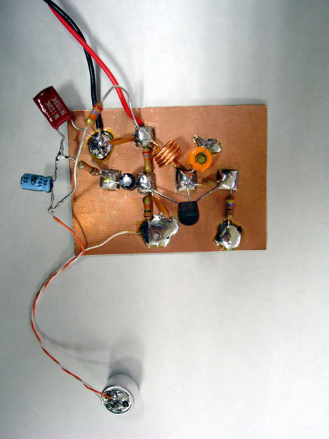
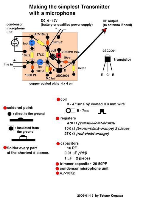
The standard model with a microphone:
This has a condenser microphone unit in it. Every version could use the same circuit. Usual microphone has not enough output to this unit, but condenser microphone unit can drive this system. See how simply it is installed--->picture
The list of components: registers, capacitors, transistor and etc.
The basic tools: soldier (less than 30 watts), wire-cutter, tweezers, and etc.
How to build and solder? A visual manual.
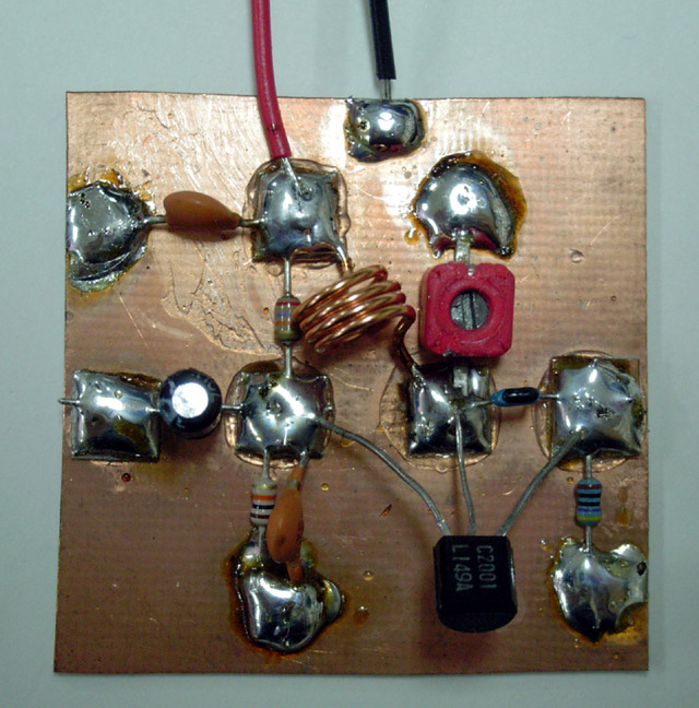
Pictures of the finished model: Standard model
FAQ
didn't work well ; stabilize the voltage ; extend the area copper plate change the frequency trimmer cap alternative transistor make the coil microphone iPod problem why need a power meter and a frequency counter
Q: The transmitter works but the airwaves are too weak. I think there might be something wrong.
A: Every transmitter using the minimum parts like this has to have harmonic signals and "spurious". So you may sometimes not receive the authentic signal. Leave your radio receiver far at least three meters from the transmitter. Don't attach any cable to the antenna terminal. Then turn the trimcap slowly. The frequency will change and you will find the most strongest signal. (See "the another Q&A below) In the 1.1 version with a variable capacitor to change the frequency, turn it very slowly until you get the most strongest signal at your radio. If you don't get, reduce the turn of the coil from 4 upto 2. When you use a variable capacitor over 10PF such as 20, 50 PF, 4 turns (I indicate in the schematic) would be too much. If you have a frequency counter, it would be easy to tune up the coil.
Q: I love the simplest transmitter. I wonder if this transmitter could be used for a practical Mini FM transmission.
A: The main problem is that the frequency is unstable. This is interesting from the perspective of radio performance, though. As the voltage of the battery is deteriorated, the transmitting frequency will be changed. In order to avoid it, you may use a stabilized power supply. It would be a bit expensiver. You don't mix with a "AC adapter". When you use a ordinary "AC adapter", you should add a voltage regulator semiconductor for 9-12 volts such as "7809" or "7812". The simplest schematic is here (jpg).
Q: This transmitter can cover only a modest radius. Is it possible to extend it?
A: If you connect it to the proper antenna, you can do it. How to make an antenna is here (pdf). For this, you have to use a thicker coaxial cable between the transmitter and the antenna. The thinest one can be used only for 1-2 meter extension. Think of the thickness of waterpipe and the length. Long extension increases the loss.
Q: I can't get "copper-coated plate". What else?
A: The schematic is supposed to use copper coated plate that is familiar with my design. When it is difficult to obtain, you can use even "porous circuit board" (jpg) that is popular in electronic hobby. The schematic is here (gif). I suggest you use the reverse side and directly solder the parts to it because this is convenient for your possible cut-and-paste and would be effective for your electro-magnetic performance.
Q: Can I change the frequency of the "basic" version? How?
A: In order to change the transmitting frequency without the trimcap, you a bit spread or compress the gap of the coil. When you do this operation, you have to have some distance (at least 3 meter) between the transmitter and the receiver (FM radio): otherwise you may be disturbed by many "spurious" (harmonic signals) and may not find the main one you want. That's why the best thing is to use a frequency counter.
Q: What is "trimmercap" in "the changable-frequency version"?
A: Don't mix it with "variable capacitance diode (varicap)" for the 1-3 W transmitter. What we need here is only for manually varying the capacitance from (theoretically) 0 to 20 PF max. There are the various types and appearances. The classical one consists of tiny brass plates and ceramics. Some of the pictures are here.
Q: I can't obtain the transistor 2SC2001. What is compatible with it?
A: There should be many replacements: 2SC2003, 2SC458, 2SC1973, 2SC3358, 2SC3580, 2SC3605, 2SD734 and so on. The European or American models such as BC337 or NTE123AP can be used, but be careful of the different position of the pins (E=Emitter, C=Collector and B=Base) depending the semiconductors. The circuit that I designed uses 2SC2001 because it is cheap and very obtainable in Tokyo.
Q: How to make a coil by myself?
A: Prepare a 5mm diameter cylindrical material and enameled wire of 0.8 mm diameter. The movie ( WMV 280KB and MPEG 1.2MB) shows how to do.
Q: I prefer to use a tunable mold coil. What kind of coil can I use?
A: I stopped showing the schematic with it because the tunable mold coil (3-4 turns) has become less obtainable now. If you can get it, just install it instead of a hand-made coil WITHOUT the trimmer capacitor.
Q: Can I build transmitter that a microphone is attached to in it?
A: You can get a "condenser microphone unit" in low price. Using this, you can build it very easily. Check the partial diagram (pdf) and the complete diagram(pdf) of the simplest transmitter with a microphone in it. When this is acrobatically soldered, here(jpg) is the example.
Q: When I connect my iPod to the audio input of this transmitter, it suddenly stops to work. What's happening?
A: The ealier model of iPod has an automatic shut-down system in it. When you pull out the plug of your headphone, it automatically stops working. When the left and right channels are short-circuited, the same thing happens. Presumably, you use a stereo cable and solderd the left (white) and right (red) lead together. Please use the left channel lead (white) only. Usually the left output is compatible with mono audio. If you, however, insist to mix the left and right output of your audio source into the transmitter, make a simple "interface" like this by two sets of 1 kiro ohm registers.
Parts List of the Most Simplest Transmitter
Registors:
1 10K Ohm 1/4 -1/8 Watt (brown-black-orange)
1 27K 1/4 -1/8 Watt (red-violet-orange)
1 470 - 500 1/4 Watt
Capacitors:
1(2) 10PF Ceramic
2 0.01MF (also indicated as 103) Ceramic
1 1 - 10 MF Electrolyiic
Coil:
1 4 turns by 0.8 mm enamel wire
Trimmer capacitor:
1 10 - 20 PF
(there are various shapes but keep the value-10_20PF)
Copper-plated board:
1 plate of 4 x 5 cm (minimum) and 0.5-1.0 mm(thick) and 4(5) small squares (5 x 5 mm)
Audio cable:
30 - 50 cm lengh of audio cable with mini-mono (or stereo) 3.5mm plug. When you use mini-stereo cable, you must use the left channel (white) only.
9 volts Battery and the snap connector


Related Links
Downloads
Building Simple FM Transmitter - Link
|
|
|
| |
Accurate LC Meter
Build your own Accurate LC Meter (Capacitance Inductance Meter) and start making your own coils and inductors. This LC Meter allows to measure incredibly small inductances making it perfect tool for making all types of RF coils and inductors. LC Meter can measure inductances starting from 10nH - 1000nH, 1uH - 1000uH, 1mH - 100mH and capacitances from 0.1pF up to 900nF. The circuit includes an auto ranging as well as reset switch and produces very accurate and stable readings. |
|
PIC Volt Ampere Meter
Volt Ampere Meter measures voltage of 0-70V or 0-500V with 100mV resolution and current consumption 0-10A or more with 10mA resolution. The meter is a perfect addition to any power supply, battery chargers and other electronic projects where voltage and current must be monitored. The meter uses PIC16F876A microcontroller with 16x2 backlighted LCD. |
|
|
|
60MHz Frequency Meter / Counter
Frequency Meter / Counter measures frequency from 10Hz to 60MHz with 10Hz resolution. It is a very useful bench test equipment for testing and finding out the frequency of various devices with unknown frequency such as oscillators, radio receivers, transmitters, function generators, crystals, etc. |
|
1Hz - 2MHz XR2206 Function Generator
1Hz - 2MHz XR2206 Function Generator produces high quality sine, square and triangle waveforms of high-stability and accuracy. The output waveforms can be both amplitude and frequency modulated. Output of 1Hz - 2MHz XR2206 Function Generator can be connected directly to 60MHz Counter for setting precise frequency output. |
|
|
|
BA1404 HI-FI Stereo FM Transmitter
Be "On Air" with your own radio station! BA1404 HI-FI Stereo FM Transmitter broadcasts high quality stereo signal in 88MHz - 108MHz FM band. It can be connected to any type of stereo audio source such as iPod, Computer, Laptop, CD Player, Walkman, Television, Satellite Receiver, Tape Deck or other stereo system to transmit stereo sound with excellent clarity throughout your home, office, yard or camp ground. |
|
USB IO Board
USB IO Board is a tiny spectacular little development board / parallel port replacement featuring PIC18F2455/PIC18F2550 microcontroller. USB IO Board is compatible with Windows / Mac OSX / Linux computers. When attached to Windows IO board will show up as RS232 COM port. You can control 16 individual microcontroller I/O pins by sending simple serial commands. USB IO Board is self-powered by USB port and can provide up to 500mA for electronic projects. USB IO Board is breadboard compatible. |
|
|
|
|
ESR Meter / Capacitance / Inductance / Transistor Tester Kit
ESR Meter kit is an amazing multimeter that measures ESR values, capacitance (100pF - 20,000uF), inductance, resistance (0.1 Ohm - 20 MOhm), tests many different types of transistors such as NPN, PNP, FETs, MOSFETs, Thyristors, SCRs, Triacs and many types of diodes. It also analyzes transistor's characteristics such as voltage and gain. It is an irreplaceable tool for troubleshooting and repairing electronic equipment by determining performance and health of electrolytic capacitors. Unlike other ESR Meters that only measure ESR value this one measures capacitor's ESR value as well as its capacitance all at the same time. |
|
Audiophile Headphone Amplifier Kit
Audiophile headphone amplifier kit includes high quality audio grade components such as Burr Brown OPA2134 opamp, ALPS volume control potentiometer, Ti TLE2426 rail splitter, Ultra-Low ESR 220uF/25V Panasonic FM filtering capacitors, High quality WIMA input and decoupling capacitors and Vishay Dale resistors. 8-DIP machined IC socket allows to swap OPA2134 with many other dual opamp chips such as OPA2132, OPA2227, OPA2228, dual OPA132, OPA627, etc. Headphone amplifier is small enough to fit in Altoids tin box, and thanks to low power consumption may be supplied from a single 9V battery. |
|
|
|
|
|
Arduino Prototype Kit
Arduino Prototype is a spectacular development board fully compatible with Arduino Pro. It's breadboard compatible so it can be plugged into a breadboard for quick prototyping, and it has VCC & GND power pins available on both sides of PCB. It's small, power efficient, yet customizable through onboard 2 x 7 perfboard that can be used for connecting various sensors and connectors. Arduino Prototype uses all standard through-hole components for easy construction, two of which are hidden underneath IC socket. Board features 28-PIN DIP IC socket, user replaceable ATmega328 microcontroller flashed with Arduino bootloader, 16MHz crystal resonator and a reset switch. It has 14 digital input/output pins (0-13) of which 6 can be used as PWM outputs and 6 analog inputs (A0-A5). Arduino sketches are uploaded through any USB-Serial adapter connected to 6-PIN ICSP female header. Board is supplied by 2-5V voltage and may be powered by a battery such as Lithium Ion cell, two AA cells, external power supply or USB power adapter. |
|
200m 4-Channel 433MHz Wireless RF Remote Control
Having the ability to control various appliances inside or outside of your house wirelessly is a huge convenience, and can make your life much easier and fun. RF remote control provides long range of up to 200m / 650ft and can find many uses for controlling different devices, and it works even through the walls. You can control lights, fans, AC system, computer, printer, amplifier, robots, garage door, security systems, motor-driven curtains, motorized window blinds, door locks, sprinklers, motorized projection screens and anything else you can think of. |
|
|
|