| |
LCD character displays can be found in espresso machines, laser printers, children’s toys and maybe even the odd toaster. The Hitachi HD44780 controller has become an industry standard for these types of displays. This tutorial will teach you the basics of interfacing with a HD44780 compatible display using some DIP switches and a few other components.

Pinout
The module that we are using is a 16 character x 2 line display that we stock over here. It uses an ST7065C controller, which is HD44780 compatible. The figure below shows the LCD module and pinout.
The last 2 pins (15 & 16) are optional and are only used if the display has a backlight.
The circuit diagram below shows the LCD module with the basic “plumbing” wired up. You will notice that pin 5 (RW) is tied to ground. This pin is use to control whether you are reading or writing to the display. Since reading from the display is very rare, most people just tie this pin to ground.
The potentiometer connected to pin 3 controls the LCD contrast.
Sending Data and Commands
Data and commands are sent to the module using the 8 data lines (pins 7-14) and the RS line (pin 4). The RS lines tells the module whether the 8 data bits relate to data or a command. The data/command is read on the falling edge of the enable line (pin 6). This means that when enable transitions from high to low, the values of D0 to D7 and RS are read.
So to send data or a command to the display, you need to
Set Enable to high
Set RS and D0-D7 desired values
Set Enable to low
There are minimum wait times between these operations, but I won’t go into them here. You can look these up in the LCD Module Datasheet. (look at the timing diagrams on page 4)
HD44780 based display modules also have a 4 bit interface mode. Under this mode the data or command is transferred to the module using 2, 4 bit nibbles. This will be discussed in more detail below.
Instructions and Characters
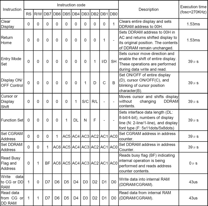
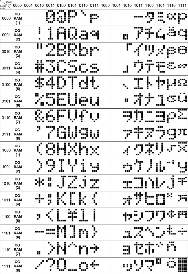
The tables below show the instruction set and character table. Click on a table to get a larger view.
Image Image
Assembling the Circuit
Normally you would drive an LCD display from a microcontroller, computer or similar device. For this exercise we will use just a series of switches. This cuts the interface to the absolute bare essentials.
The circuit being built is shown below.
The photo below shows the circuit, on a breadboard without the LCD module. I’ve also added a small L7805 based power supply on the right hand side of the board. You can get the parts for the power supply here.
The Register Select and data lines are pulled down using a 10K resistor and when the dip switch is closed, those lines go high. The enable line on the other hand is pulled high and when the button is pressed, the line goes to ground. The enable button has a 10nF capacitor to de-bounce it.
Before inserting the LCD module into the breadboard, you will need to solder a row of 16 pin single row headers. This is shown in the photo below.
Next we insert the LCD module into the breadboard and power it on. When you insert the module into the breadboard, you need to be gentle and work the pins in slowly because the pins are a bit thicker than you would normally use with a breadboard.
If you don’t see the pattern shown below, you will need to turn the contrast pot till you do. This pattern is the default pattern for an uninitialized LCD display.
Interfacing via the 8 bit mode
To interface to the display and output text we need to
Initialise the display,
Set entry mode, and
Send a sequence of characters to display
So to output the text “Hello World” we need to power up the device then enter the following sequence of Data/Commands, pressing Enable at the end of each Data/Command block.
RS D7 to D0 Description
0 0 0 1 1 – 1 0 0 0 Function set, 8 bit, 2 lines, 5×7
0 0 0 0 0 – 1 1 1 1 Display ON, Cursor On, Cursor Blinking
0 0 0 0 0 – 0 1 1 0 Entry Mode, Increment cursor position, No display shift
1 0 1 0 0 – 1 0 0 0 H
1 0 1 1 0 – 0 1 0 1 e
1 0 1 1 0 – 1 1 0 0 l
1 0 1 1 0 – 1 1 0 0 l
1 0 1 1 0 – 1 1 1 1 o
1 0 0 1 0 – 0 0 0 0 space
1 0 1 0 1 – 0 1 1 1 w
1 0 1 1 0 – 1 1 1 1 o
1 0 1 1 1 – 0 0 1 0 r
1 0 1 1 0 – 1 1 0 0 l
1 0 1 1 0 – 0 1 0 0 d
Interfacing via the 4 bit mode
The main benefit of the 4 bit mode is that less data lines are required. In this mode D3 to D0 are tied to ground and data/commands are transferred 1, 4 bit nibble at a time.
RS D7 to D0 Description
0 0 0 1 0 – 0 0 0 0 Set to 4 bit operation (note: 1 nibble operation)
0 0 0 1 0 – 0 0 0 0 Function set, 8 bit
0 1 0 0 0 – 0 0 0 0 2nd nibble
0 0 0 0 0 – 0 0 0 0 Display ON, Cursor On, Cursor Blinking
0 1 1 1 1 – 0 0 0 0 2nd nibble
0 0 0 0 0 – 0 0 0 0 Entry Mode, Increment cursor position, No display shift
0 0 1 1 0 – 0 0 0 0 2nd nibble
1 0 1 0 0 – 0 0 0 0 H
1 1 0 0 0 – 0 0 0 0 2nd nibble
1 0 1 1 0 – 0 0 0 0 e
1 0 1 0 1 – 0 0 0 0 2nd nibble
1 0 1 1 0 – 0 0 0 0 l
1 1 1 0 0 – 0 0 0 0 l
1 0 1 1 0 – 0 0 0 0 l
1 1 1 0 0 – 0 0 0 0 l
1 0 1 1 0 – 0 0 0 0 o
1 1 1 1 1 – 0 0 0 0 2nd nibble
1 0 0 1 0 – 0 0 0 0 space
1 0 0 0 0 – 0 0 0 0 2nd nibble
1 0 1 0 1 – 0 0 0 0 w
1 0 1 1 1 – 0 0 0 0 2nd nibble
1 0 1 1 0 – 0 0 0 0 o
1 1 1 1 1 – 0 0 0 0 2nd nibble
1 0 1 1 1 – 0 0 0 0 r
1 0 0 1 0 – 0 0 0 0 2nd nibble
1 0 1 1 0 – 0 0 0 0 l
1 1 1 0 0 – 0 0 0 0 2nd nibble
1 0 1 1 0 – 0 0 0 0 d
1 0 1 0 0 – 0 0 0 0 2nd nibble
That’s about as easy as it gets!
In the next part we will discuss how to hookup the module to a microcontroller and get it to do the hard work for you.


Related Links
Downloads
Character LCD Displays - Link
|
|
|
| |
Accurate LC Meter
Build your own Accurate LC Meter (Capacitance Inductance Meter) and start making your own coils and inductors. This LC Meter allows to measure incredibly small inductances making it perfect tool for making all types of RF coils and inductors. LC Meter can measure inductances starting from 10nH - 1000nH, 1uH - 1000uH, 1mH - 100mH and capacitances from 0.1pF up to 900nF. The circuit includes an auto ranging as well as reset switch and produces very accurate and stable readings. |
|
PIC Volt Ampere Meter
Volt Ampere Meter measures voltage of 0-70V or 0-500V with 100mV resolution and current consumption 0-10A or more with 10mA resolution. The meter is a perfect addition to any power supply, battery chargers and other electronic projects where voltage and current must be monitored. The meter uses PIC16F876A microcontroller with 16x2 backlighted LCD. |
|
|
|
60MHz Frequency Meter / Counter
Frequency Meter / Counter measures frequency from 10Hz to 60MHz with 10Hz resolution. It is a very useful bench test equipment for testing and finding out the frequency of various devices with unknown frequency such as oscillators, radio receivers, transmitters, function generators, crystals, etc. |
|
1Hz - 2MHz XR2206 Function Generator
1Hz - 2MHz XR2206 Function Generator produces high quality sine, square and triangle waveforms of high-stability and accuracy. The output waveforms can be both amplitude and frequency modulated. Output of 1Hz - 2MHz XR2206 Function Generator can be connected directly to 60MHz Counter for setting precise frequency output. |
|
|
|
BA1404 HI-FI Stereo FM Transmitter
Be "On Air" with your own radio station! BA1404 HI-FI Stereo FM Transmitter broadcasts high quality stereo signal in 88MHz - 108MHz FM band. It can be connected to any type of stereo audio source such as iPod, Computer, Laptop, CD Player, Walkman, Television, Satellite Receiver, Tape Deck or other stereo system to transmit stereo sound with excellent clarity throughout your home, office, yard or camp ground. |
|
USB IO Board
USB IO Board is a tiny spectacular little development board / parallel port replacement featuring PIC18F2455/PIC18F2550 microcontroller. USB IO Board is compatible with Windows / Mac OSX / Linux computers. When attached to Windows IO board will show up as RS232 COM port. You can control 16 individual microcontroller I/O pins by sending simple serial commands. USB IO Board is self-powered by USB port and can provide up to 500mA for electronic projects. USB IO Board is breadboard compatible. |
|
|
|
|
ESR Meter / Capacitance / Inductance / Transistor Tester Kit
ESR Meter kit is an amazing multimeter that measures ESR values, capacitance (100pF - 20,000uF), inductance, resistance (0.1 Ohm - 20 MOhm), tests many different types of transistors such as NPN, PNP, FETs, MOSFETs, Thyristors, SCRs, Triacs and many types of diodes. It also analyzes transistor's characteristics such as voltage and gain. It is an irreplaceable tool for troubleshooting and repairing electronic equipment by determining performance and health of electrolytic capacitors. Unlike other ESR Meters that only measure ESR value this one measures capacitor's ESR value as well as its capacitance all at the same time. |
|
Audiophile Headphone Amplifier Kit
Audiophile headphone amplifier kit includes high quality audio grade components such as Burr Brown OPA2134 opamp, ALPS volume control potentiometer, Ti TLE2426 rail splitter, Ultra-Low ESR 220uF/25V Panasonic FM filtering capacitors, High quality WIMA input and decoupling capacitors and Vishay Dale resistors. 8-DIP machined IC socket allows to swap OPA2134 with many other dual opamp chips such as OPA2132, OPA2227, OPA2228, dual OPA132, OPA627, etc. Headphone amplifier is small enough to fit in Altoids tin box, and thanks to low power consumption may be supplied from a single 9V battery. |
|
|
|
|
|
Arduino Prototype Kit
Arduino Prototype is a spectacular development board fully compatible with Arduino Pro. It's breadboard compatible so it can be plugged into a breadboard for quick prototyping, and it has VCC & GND power pins available on both sides of PCB. It's small, power efficient, yet customizable through onboard 2 x 7 perfboard that can be used for connecting various sensors and connectors. Arduino Prototype uses all standard through-hole components for easy construction, two of which are hidden underneath IC socket. Board features 28-PIN DIP IC socket, user replaceable ATmega328 microcontroller flashed with Arduino bootloader, 16MHz crystal resonator and a reset switch. It has 14 digital input/output pins (0-13) of which 6 can be used as PWM outputs and 6 analog inputs (A0-A5). Arduino sketches are uploaded through any USB-Serial adapter connected to 6-PIN ICSP female header. Board is supplied by 2-5V voltage and may be powered by a battery such as Lithium Ion cell, two AA cells, external power supply or USB power adapter. |
|
200m 4-Channel 433MHz Wireless RF Remote Control
Having the ability to control various appliances inside or outside of your house wirelessly is a huge convenience, and can make your life much easier and fun. RF remote control provides long range of up to 200m / 650ft and can find many uses for controlling different devices, and it works even through the walls. You can control lights, fans, AC system, computer, printer, amplifier, robots, garage door, security systems, motor-driven curtains, motorized window blinds, door locks, sprinklers, motorized projection screens and anything else you can think of. |
|
|
|


