| |
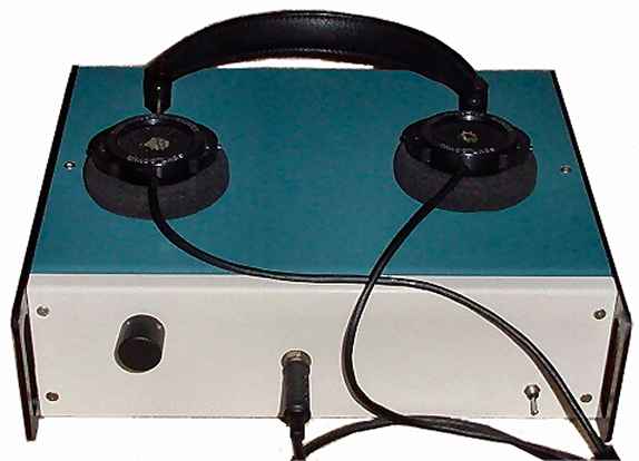
Class A Headphone Amplifier |
|
This class A headphone amplifier can output up to 0.5W into a 32-ohm headphones. I built this headphone amplifier for dynamic headphones based on my rules of proper audio design. People who know my designs will realize that this headphone amplifier is much more than just a headphone amp. It is a pure class A design containing a new never-before-seen servo loop that is not part of the audio signal chain in any way. The sound of this class A headphone amplifier is just amazing.
Capacitors in the audio signal path are BAD. Even the best silver-mica or poly caps exhibit non-linearities at low voltage levels. Capacitors belong in power supply sections and nowhere else. Capacitors used to compensate an amplifer generally mean that the amplifier is otherwise unstable, with poles in the right half plane and is therefore a bad design.
Transformers in the audio signal path are even worse: non-linearities in the gain structure, parasitic capacitance between windings, impedance problems.... Transformers belong in linear power supplies and nowhere else.
Ultra high open loop gain: REAL, REAL BAD!!! That basically means anything with an opamp in it. Opamp circuits with open loop gains of 10,000 or more require large amounts of feedback to make them usable. While this reduces THD, the intermodulation products, and especially the transient intermodulation products are much higher than they should be.
Servo loops MUST NOT be in the audio feedback loop. This rule is also very important. Two of my favorite high-end audio electronics manufacturers put servo loops into the minus input of their amplifiers. Most other manufacturers that use servo loops do the same thing. opamps used for servo loops do not have an output impedance low enough to make them suitable for this purpose. Furthermore the dynamic output impedance of opamps adds non-linearities to the audio when put in series with the gain resistor on the minus input.
Kind of makes designing ultra high quality audio stuff tough. My design goals in this amplifier were: keep the gain per stage down, keep all stages in class A, keep the differential front end from coming even close to clipping by the use of a current source. Because the amplifier has a low overall gain and little feedback, a servo helps to prevent DC voltages at the output. In general, if the open loop gain is kept down to eliminate all or most of transient intermodulation distortion, then the amplifier circuitry has to be extremely linear and low distortion. Otherwise, you end up with something that measures and performs like crap.
The Circuit
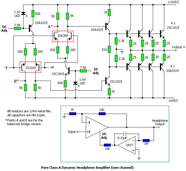
The schematic for the standard (non-bridged output) version of the headphone amplifier is shown in figure 1. The open loop gain of the amplifer is about 35. Even with the feedback removed, the THD is less than .01%. That's important because the more linear an amplifier is without feedback, the more the THD, IM and TIM distortions are reduced to unmeasurable levels with feedback added.
Stage 1 is a dual FET fully-differential fully-balanced front-end. The idling current is 2mA total per dual FET (1mA per FET) and 4mA for the complete front-end stage which consists of both dual FETs. The dual FETs generate the bias which runs the second stage, and keeps it and the resulting output section in class A at all times. The FETs are ultra low noise dual units specifically designed for audio uses. The total voltage gain of the first stage is 50.
Stage 2 is the driver stage. It is a standard class A voltage amplifier - in this case used as a voltage shifter. The voltage gain is 0.5 and the idling current 4.3mA.
The push-pull class A output stage is a series of paralleled emitter follower, current buffers. The voltage gain is 0.9 and the current gain is 75. The idling current is 15mA per transistor (or 60mA for the 8 transistors off the +16VDC rail and 60mA for the 8 transistors off the -16VDC rail). I have designed the output section to run at what I have determined is the sweet spot for these transistors, which is 15mA each. Yeah, it gets hot; its supposed to get hot (but not hot enough to require heatsinks). It's not possible to make an amplifier with an output impedance less than 0.1 ohm without throwing around a fair amount of current.
The servo circuit is new: most of the servo designs (Mark Levinson and Krell, for example) put the output of the DC servo back into the - leg of the amplifier. I just do not like this. That puts the noise and non-linearities of the opamp inside the audio loop.
My servo feeds back to the current sources for the dual FETs in stage 1. Like all servos, it is an integrator. Due to the large (relatively) integration capacitor and the 1 meg resistor, the frequency of this filter is 0.05 Hz. With even a decent opamp, the servo's noise is in the tens of microvolts, and does not affect the operation of the current sources significantly.
The servo opamp in this amplifier measures the DC at the output, if any, integrates it and applies it to the midpoint of the two LEDs. The LEDs do have a slight change in voltage with respect to current, about 3 or 4%, and that is enough to make the servo work. Notice that if the transistors or the resistors are very poorly matched, the servo will not work because its total control range is at most 10%. Most standard servos (such as the Mark Levinson or Krell servos) have a much wider range.
For high impedance headphones, a little DC will not hurt the phones. With the low impedance Grados, even 0.1VDC over a long period of time will definitely damage and/or change the sound. If all the parts are hand matched, the power supplies are exactly the same and all the resistors are really good quality, the amp should be stable and should not drift. In that case, the servo could be omitted or replaced with a 20K trimmer pot wired from +16VDC to -16VDC, with the wiper going to the DC adjust pin. The prototype uses 0.05% tolerance resistors, and I hand-matched the transistors. The output DC is less than 6mV and has stayed absolutely stable for the few months I have had the unit.
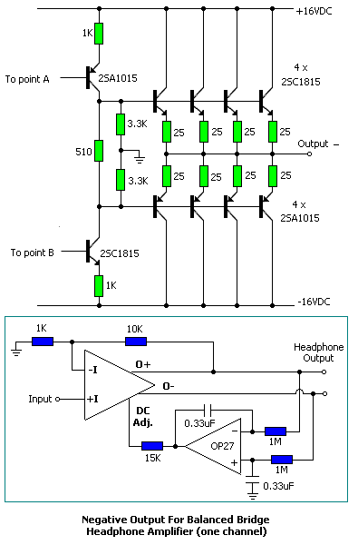
Schematic for - output for bridged version of amplifier.
Figure 2
The amp gives about 0.5W into 32 ohms. In the classical definition of class A, the top transistors would be sourcing 120mA and the bottom transistors sinking 0mA. However the two 3k resistors in the second stage actually prevent the total shutdown of either transistor bank by keeping the opposing stage at an absolute minimum of 5mA. In any case, 0.5W into Grados is unbelieveably loud.
The balanced bridge output version of the amplifier (figure 2) is for those headphones that can be wired as dual mono (see the addendum for instructions on converting a pair of standard Grado SR-80 headphones into dual mono headphones). It has twice the voltage swing, twice the slew rate and 4 times the output power (competes with the $2600 HeadRoom balanced Max amplifier).
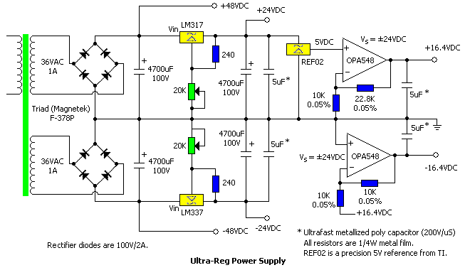
Schematic of power supply.
The ultra-regulation of the power supply (figure 3) is so over the top and unnecessary that most, if not all, people building this amplifier would not even notice the difference. However there are a number of benefits to this design. First its a dual tracking design. Because the open loop gain of the amp is low, its common mode rejection due to the power supply is not great. However if both the + and - voltage rails move up and down the same amount, there is no bias drift.
Because of the pre-regulators, the total line/load variations are under 0.0001%. The fast capactors allow the power supply to react rapidly and in a controlled manner with highly reactive loads like the Grados. The opamp outputs are active in both directions; they can push or pull to keep the power supply at exactly the right point. The power supply design was an attempt to come up with the absolutely best power supply I could. It is even quieter than batteries.
Construction
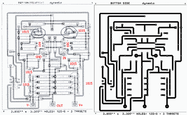
The prototype was built with point to point wiring, keeping it tight and tiny. The layout is exactly as shown on the schematic, which is also why the board is only one layer. Although the amplifier is easy to build without a PC board, I designed one for the amplifier. Each board (you need 2 for the standard amplifier or 4 for the bridged version) is 3.3" x 3.8". In a few months, I may redo the board in one of the systems where I can ship the file over the internet and get boards back (like expresspcb.com).
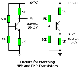
The servo's total control range is at most 10%, so the some of the servo-related parts must be closely matched for optimal operation of the servo. The 500 ohm resistors, 1.6V LEDs, bias transistors and second stage transistors must be matched to within 0.5% or even 0.25% for optimal operation of the servo (the dual FETs are already matched). To match the LEDs, put one in series with a 10k resistor, hook it to 15VDC and measure the voltage across it. Do it to a few of them and pick the closest match.
Circuits for matching the NPN and PNP transistors.
I used a Tektronix curve tracer to match the transistors. Figure 4 shows two circuits for matching the beta (gain) of the NPN and PNP transistors using just a voltmeter. Simply measure (and match) the voltage of each transistor's collector with respect to ground. It should be in the range of 10V to 11V for the NPNs or 5V to 6V for the PNPs.
There are no substitutes for the FETs. The PNP and NPN transistors in the prototype were the MPS8099 and MPS8599. Onsemi has discontinued them, but there are still lots available. I am buying all my transistors now over the web from MCM Electronics. I have had too much trouble with everyone else. The 2SA1015 PNPs are $0.46 each; the 2SC1815 NPNs are $0.41 each. The 2SJ109 p-channel dual FET is about $6.50; its n-channel counterpart is $5.90. By the time you add it all up, it's still under the minimum MCM order, so you've got to buy something else.
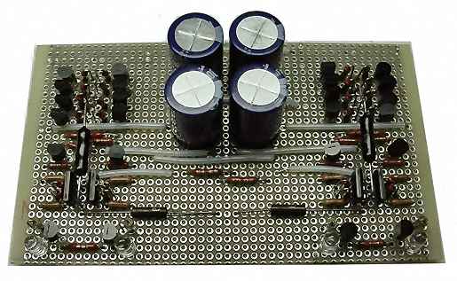
Stuffed PC board.
The high-speed 5uF capacitors in the power supply are not critical. They satisfy the "lunatic fringe" in audio. These capacitors are rated for a slew rate (dv/dt) of about 4 times a standard capacitor. They cost $7.50 from the Illinois Capacitor Company. Similarly, the opamps in the power supply are not critical. In the prototype power supply, I used the Apex PA09, which has a 400V/uS slew rate and costs $167 each (remember, I am crazy). Normal people should use the Texas Instruments OPA549 (10V/uS) that cost $11 each. The LM3xx regulators are heatsinked (dissipating at least 3W each, 6W for the bridged version of the amplifier).
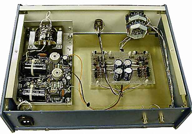
The enclosure is the Mod.U.Line by Precision Fabrication Technologies Inc. (part number 03-1209-BW), available from Newark Electronics. They are about $85 a piece these days. The aluminum enclosure is easy of use, easy to punch, and keeps a decent paint job. The headphone jack is a cheap Radio Shack one. Although it works fine. I have since gotten some Neutrik connectors which I will put in at some point. In theory, there is a ground loop between the RCA jacks on the back plate and the headphone jack on the front plate. Although the 60 Hz hum is about 110 db down, the Neutrik jacks are isolated and will make this problem go away.
Interior of amplifier chassis.
The amplifier's output is voltage limited (not current limited) because the second stage runs out of voltage swing - typically about 6V rms. For a 32 ohm load, the maximum output power is 1.125W (0.1875A). For a 300 ohm load such as the Sennheiser HD600, the maximum output power is 0.125W (0.02A). To increase the maximum output voltage to, say, 10V rms, try increasing the power supply to ±20VDC and change the 500 ohm resistors in the current sources/sinks to 600 ohms (or ±24VDC and 700 ohms - but careful not to fry the output transistors).
The bridged version will output 4.5W into the 32-ohm Grados and 0.5W into the 300-ohm Sennheiser HD600. At full blast, the amp does drop out of class A, but at levels that will fry your ears anyway.
The Result
Adjustments: In the power supply, adjust the top 20K trimmer pot for +24 volts at the tap after the LM317. Then adjust the bottom 20K trimmer pot for -24V at the tap after LM337. (Note: the ±48V taps are shown for reference only; they are not actually used by the amplifier.) If the servo has been replaced with a 20K trimmer pot, adjust the trimmer so that the output measures 0VDC. Anything under 25mV is fine.
I listened to the balanced HeadRoom Max at The Home Electronics Show. The low frequency bass slam is absent from the unit. When I listened to the BlockHead ($3333) and compared it to my unbalanced/balanced amp, the same thing happened. Without the kaboom, it's just not as much fun to listen to.
This amp gives the Grados and Etymotic Canalphones a fuller and much more upfront sound than the built-in headphone jacks on various players - the bass has a snap to it that it never used to have. And the image moves from around your head to the center of your nose. The Etymotics tend to sound kind of thin and distant with other amps. In general, I have to say that this amp produces bass that is much more solid - similar to putting the microphone in front of a bass violin instead of inside it.
Related Links
Downloads
Class A Headphone Amplifier - Link
|
|
|
| |
Accurate LC Meter
Build your own Accurate LC Meter (Capacitance Inductance Meter) and start making your own coils and inductors. This LC Meter allows to measure incredibly small inductances making it perfect tool for making all types of RF coils and inductors. LC Meter can measure inductances starting from 10nH - 1000nH, 1uH - 1000uH, 1mH - 100mH and capacitances from 0.1pF up to 900nF. The circuit includes an auto ranging as well as reset switch and produces very accurate and stable readings. |
|
PIC Volt Ampere Meter
Volt Ampere Meter measures voltage of 0-70V or 0-500V with 100mV resolution and current consumption 0-10A or more with 10mA resolution. The meter is a perfect addition to any power supply, battery chargers and other electronic projects where voltage and current must be monitored. The meter uses PIC16F876A microcontroller with 16x2 backlighted LCD. |
|
|
|
60MHz Frequency Meter / Counter
Frequency Meter / Counter measures frequency from 10Hz to 60MHz with 10Hz resolution. It is a very useful bench test equipment for testing and finding out the frequency of various devices with unknown frequency such as oscillators, radio receivers, transmitters, function generators, crystals, etc. |
|
1Hz - 2MHz XR2206 Function Generator
1Hz - 2MHz XR2206 Function Generator produces high quality sine, square and triangle waveforms of high-stability and accuracy. The output waveforms can be both amplitude and frequency modulated. Output of 1Hz - 2MHz XR2206 Function Generator can be connected directly to 60MHz Counter for setting precise frequency output. |
|
|
|
BA1404 HI-FI Stereo FM Transmitter
Be "On Air" with your own radio station! BA1404 HI-FI Stereo FM Transmitter broadcasts high quality stereo signal in 88MHz - 108MHz FM band. It can be connected to any type of stereo audio source such as iPod, Computer, Laptop, CD Player, Walkman, Television, Satellite Receiver, Tape Deck or other stereo system to transmit stereo sound with excellent clarity throughout your home, office, yard or camp ground. |
|
USB IO Board
USB IO Board is a tiny spectacular little development board / parallel port replacement featuring PIC18F2455/PIC18F2550 microcontroller. USB IO Board is compatible with Windows / Mac OSX / Linux computers. When attached to Windows IO board will show up as RS232 COM port. You can control 16 individual microcontroller I/O pins by sending simple serial commands. USB IO Board is self-powered by USB port and can provide up to 500mA for electronic projects. USB IO Board is breadboard compatible. |
|
|
|
|
ESR Meter / Capacitance / Inductance / Transistor Tester Kit
ESR Meter kit is an amazing multimeter that measures ESR values, capacitance (100pF - 20,000uF), inductance, resistance (0.1 Ohm - 20 MOhm), tests many different types of transistors such as NPN, PNP, FETs, MOSFETs, Thyristors, SCRs, Triacs and many types of diodes. It also analyzes transistor's characteristics such as voltage and gain. It is an irreplaceable tool for troubleshooting and repairing electronic equipment by determining performance and health of electrolytic capacitors. Unlike other ESR Meters that only measure ESR value this one measures capacitor's ESR value as well as its capacitance all at the same time. |
|
Audiophile Headphone Amplifier Kit
Audiophile headphone amplifier kit includes high quality audio grade components such as Burr Brown OPA2134 opamp, ALPS volume control potentiometer, Ti TLE2426 rail splitter, Ultra-Low ESR 220uF/25V Panasonic FM filtering capacitors, High quality WIMA input and decoupling capacitors and Vishay Dale resistors. 8-DIP machined IC socket allows to swap OPA2134 with many other dual opamp chips such as OPA2132, OPA2227, OPA2228, dual OPA132, OPA627, etc. Headphone amplifier is small enough to fit in Altoids tin box, and thanks to low power consumption may be supplied from a single 9V battery. |
|
|
|
|
|
Arduino Prototype Kit
Arduino Prototype is a spectacular development board fully compatible with Arduino Pro. It's breadboard compatible so it can be plugged into a breadboard for quick prototyping, and it has VCC & GND power pins available on both sides of PCB. It's small, power efficient, yet customizable through onboard 2 x 7 perfboard that can be used for connecting various sensors and connectors. Arduino Prototype uses all standard through-hole components for easy construction, two of which are hidden underneath IC socket. Board features 28-PIN DIP IC socket, user replaceable ATmega328 microcontroller flashed with Arduino bootloader, 16MHz crystal resonator and a reset switch. It has 14 digital input/output pins (0-13) of which 6 can be used as PWM outputs and 6 analog inputs (A0-A5). Arduino sketches are uploaded through any USB-Serial adapter connected to 6-PIN ICSP female header. Board is supplied by 2-5V voltage and may be powered by a battery such as Lithium Ion cell, two AA cells, external power supply or USB power adapter. |
|
200m 4-Channel 433MHz Wireless RF Remote Control
Having the ability to control various appliances inside or outside of your house wirelessly is a huge convenience, and can make your life much easier and fun. RF remote control provides long range of up to 200m / 650ft and can find many uses for controlling different devices, and it works even through the walls. You can control lights, fans, AC system, computer, printer, amplifier, robots, garage door, security systems, motor-driven curtains, motorized window blinds, door locks, sprinklers, motorized projection screens and anything else you can think of. |
|
|
|