The Clock Controller V1.1was designed to be an exemplary of using 'C' language to control timer0interrupt, 7-segment LED and keypad scanning. It provides 1-bit sink currentdriving output, for driving a relay, opto-triac, say. Many projects requiring7-segment display and keypad interfacing may get the idea from the Clockcircuit and software.
Hardware
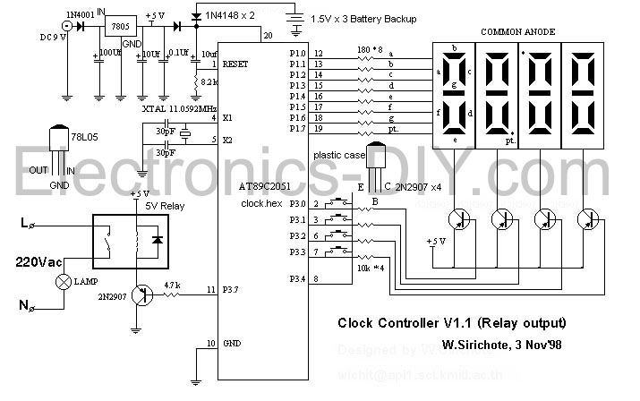
Figure 1 shows a circuitdiagram of the Clock Controller V1.1. P10-P1.7 drives 7-segment commonanode LED with sink current. P3.0-P3.3 also drives a base pin of 4-PNPtransistor, 2n2907 with sink current. As shown in the figure, the 2nd 2-digitLED that connected to P3.2 and P3.3 is rotated 180 degrees to the 1st 2-digitallowing the pt. segment to be used for 1 second blinking. P3.0-P3.3 alsoconnects four momentary switches while the other legs are tied to inputport P3.4. During display and key switch scanning, a logic '0' is shiftedfrom P3.0 to P3.3, if there was a key pressed, P3.4 then became low.P3.7 is a 1-bit sink current driving, an example in the circuit uses a2n2907 to drive a small electromechanical relay 5V, say.
Figure 1: Schematic Diagramof the Clock V1.1
Software
The program clock.cwas written in ‘C’ language and was complied by Micro-C Compiler from DunfiledDevelopment Systems. The memory model is TINY. The hex file of clock.csuitable for downloading by Easy-Downloaderis clock.hex.
The Clock1.cwas modified for C51 compiler. The function that updates real-time clockwas moved into timer0 interrupt service routine. The HEX file is Clock1.hexsmaller than compiled by Micro-C.
I got many requests askingmodification of the source code. Now you can modify the source code byyourself with the free compiler sdcc for 8051. Here is the source codeof new firmware, clock2.c and the hex file, clock2.hex.Please test it and let me know the result. I haven't tested my hardwareyet, because I cannot find it now. This project is quite long time ago.You may add your code or modify whatever you like to have using sdcc! Youmay download the sdcc here, sdcc.zip.
Practice
The function time( ) in clock.cwas not put in the timer0 service routine, there's a bit delay at scanLED() function making the clock delay, try write a function that make adjustmentof the clock.
With C51 compiler, there's aspace for more functions to put in, write a function that saves a secondtime on and off.
Heavy Load Driving
I suggest to use a zero switchsolid-state relay for driving heavy loads (>10A). Most solid state relay'sinput can be driven with 3-30Vdc without any problems.
Contribution to Clock ControllerProject
Sridhar Vittalrao designedthe PCB layout (Protel), Clock.zip.
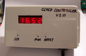
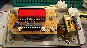
One day I found a small 7-segment LED with multiplex connection. It is nice to be used as the display for clock controller. So I spent my weekend built the board. Below are the pictures for outlook and internal. The board is quite small. The output has small relay for 0.5A AC load.
This version has only three buttons. We can set current hour and min easily. The preset time on/off for relay control output are defined in the program.
// preset set time on/off are predefined in rom, user may change it here
#define onHour1 19
#define onMin1 00
#define offHour1 21
#define offMin1 30
Also if you need more period to turn on/off you can add, say onHour2, onMin2, offHour2, and offMin2. And provide the function that compares such period. It will be the same as function comparetime. Or you may insert at if statements. When reset, the board will turn output off, until user set current time, the clock will run again. This prevent improper output firing.
void comparetime()
{
if(flag1 & 0x40) // compare time only when user enter new time
{
if(flag1 & 0x01)
{
flag1 &= ~0x01;
if(hour == onHour1 && min == onMin1)
opto = 0x7f; /* clear P3.7 turning opto on */
if(hour == offHour1 && min == offMin1)
opto = 0xff; /* set bit P3.7 turning opto off */
}
}
}
Updated Schematic
http://electronics-diy.com/schematics/1148/clock2.pdf
/*

   CLOCK CONTROLLER V2.0

   89C2051 + 4-digit 7-SEG led + 2-key switch

   Simple Digital Clock demostrates scanning LED and key switch.

   The clock has 1-bit output port P3.7 for driving AC load through MOC3040+triac.


           *    ****       ****    ****

           *   *    *  *  *    *  *    *

           *   *    *     *    *  *    *

           *    ****      *    *  *    *

           *   *    *     *    *  *    *

           *   *    *  *  *    *  *    *

           *    ****       ****    ****


              set                 set

             HOUR                 MIN


   Copyright (c) 2006 WICHIT SIRICHOTE, kswichit@kmitl.ac.th

*/


#include                /* special function register declarations   */

                                  /* for the AT89C52       */

#include


// preset set time on/off are predefined in rom, user may change it here


#define onHour1 19

#define onMin1 00

#define offHour1 21

#define offMin1 30


unsigned  char sec100,sec,sec5,min,hour,flag1,command,temp,opto;

unsigned char i,digit, buffer[4];

char cputick,key,delay,count1;

unsigned char convert[10] = {0x3F,0x06,0x5b,0x4f,0x66,0x6d,0x7d,0x07,0x7f,0x6f};


void pause(int);

void scanLED();


void setmin();

void sethour();

void showOnce();

void savetimeOff1();


void time();

void timeToBuffer();

void blink();

void offmsd();

void keyexe();

void keydelay();

void comparetime();


void timer0int (void)  interrupt 1  using 1  {

	TH0 |= 0xd8;  // reload timer 0 with d8f0h

	TL0 |= 0xf0;

    cputick++;

	time();       // update realtime clock


}


void main()

{

  EA = 1;

  ET0 = 1;  // or IE |= 0x82;   /* set bit EA and Timer0 enable */

  TMOD |= 0x01; /* timer 0 run 16 bit counter */

  TR0 = 1; //or TCON |= 0x10; /* run timer 0 */

  opto = 0xff;

  cputick = 0;

  hour = 18;

  min = 0;

  sec = 0;

  key = -1;

  flag1 = 0;


  count1 = 0;

  buffer[0] = 0x40;

  buffer[1] = 0x40;

  buffer[2] = 0x40;

  buffer[3] = 0x40;


  while(1)

  {

    while ( cputick < 1)

    scanLED();


    cputick = 0;


/*------------- the following tasks execute every 10ms ------*/


    timeToBuffer();

    blink();

    offmsd();

    keyexe();

    keydelay();

    comparetime();


/*-----------------------------------------------------------*/

   }

}


/* update real-time clock  */

void time ()


{

   if (++sec100 >= 100)       /* 100 * 10 ms = 1 s */

   {sec100 = 0;

    flag1 |= 0x05;   /* set bit 0, bit 2 */

    temp = 50;

    if (++sec >= 60)

    {sec = 0;

     flag1 |= 0x02; /* set bit 1 */

       if (++min >= 60)

     {min = 0;

         if (++hour >= 24)

     {hour = 0;


    }

  }

 }

}

}


void scanLED() /* scan 4-digit LED and 4-key switch, if key pressed key = 0-3

else key = -1 */


{

    int i;

    digit = 0x08;

    key = -1;

    for( i = 0; i < 4; i++)  /* 4-DIGIT scanning */

    {

        P3 = ~digit & opto;  /* send complement[digit] */

        P1 = buffer[i];  /* send segment */

        pause(10);         /* delay a while */

        P1 = 0x00;        /* off LED */

        if ((P3 & 0x10) == 0) /* if key pressed P3.4 became low */

           key = i;       /* save key position to key variable */

        digit>>=1;        /* next digit */

    }

}


void timeToBuffer()

{

  if(flag1&0x40) // run only when any key was pressed

  {

    buffer[0] = convert[min%10];

    buffer[1] = convert[min/10];

    buffer[2] = convert[hour%10];

    buffer[3] = convert[hour/10];

  }

}


void blink()

{

    if(flag1 & 0x04) /* check bit 2 if set decrement temp until zero */

     {temp--;

        if (temp != 0)

                {

                  buffer[2] |= 0x80;

                }

                else( flag1 &= ~0x04);

      }

}


void keyexe()

{

    if (key != -1)

    {

        if ((flag1 & 0x80) == 0)  /* within 0.5 sec after 1st press

                                    the following execution is not allowed */

            {

                flag1 |= 0x80;

                delay = 50;


      switch(key){

        case (0): /* key position 0 */

        ;

        break;

        case (1): /* key position 1 */

        ;

        break;

        case (2): /* key position 2 */

        setmin(); /* service key 2 */

        break;

        case (3): /* key position 3 */

        sethour();

                  }

                }


    }

}


void sethour()

{

    flag1 |= 0x40; // enable time upldate

    if ( ++hour== 24) hour = 0;


}


void setmin()

{

     flag1 |= 0x40; // enable time upldate

    sec = 0;

    if( ++min == 60 ) min = 0;

}


void keydelay()

{

    if (flag1 & 0x80)

        {

          delay--;

        if(delay == 0) flag1 &= ~0x80;

        }

}


void comparetime()

{

  if(flag1 & 0x40) // compare time only when user enter new time

  {

    if(flag1 & 0x01)

    {

        flag1 &= ~0x01;

    if(hour == onHour1 && min == onMin1)

            opto = 0x7f; /* clear P3.7 turning opto on   */

    if(hour == offHour1 && min == offMin1)

            opto = 0xff; /* set bit P3.7 turning opto off */

    }

   }

}


void offmsd()


{

    if (buffer[3] == 0x3f)    /* if msd = '0' then put blank unstead */

       buffer[3] = 0x00;

}


void pause(j)

int j;

{

   int i;

   for (i = 0; i < j; i++) continue;

}