| |
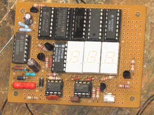
I wanted a digital AC voltmeter to measure the output range from 0 to 150VAC with reasonable accuracy. Sure I could buy some premade DVM packages or use a microcontroller with a built-in ADC, but I wanted to make one from scratch myself using readily available parts I had on hand. I aimed for reasonable accuracy so I chose to have a 2 and a half display for the voltage, meaning the meter reads from 000 to 199. Below is the schematic of the AC DVM.

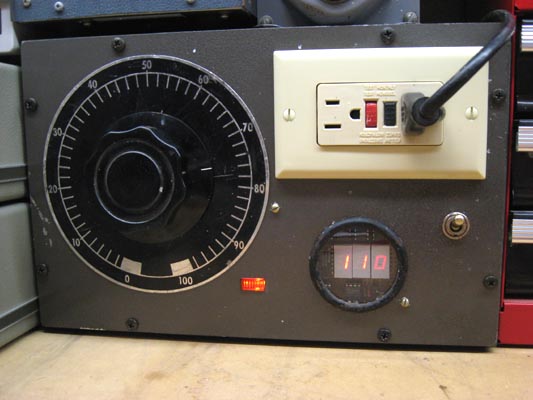
My variable AC power supply has gone through several revisions over the years. It started out as a simple unenclosed variac (variable autotransformer) and electrical outlet mounted on a block of wood. I eventually put it in the case of what used to be an old audio signal generator for safety and appearance. Among the other added features, I used a 0-250VAC analog meter that I had on hand to display the output voltage because otherwise it was annoying to whip out the multimeter to monitor the voltage coming out of the variac. Over the years I realized that the meter was inaccurate and simply useless, so a new readout was necessary.
I used a voltage-controlled PWM circuit to convert an analog DC voltage to a pulse duty cycle. To do this, a 555 timer is used to generate a sawtooth wave at about 500Hz that is fed into a comparator to compare against the measured analog DC voltage. The output of the comparator has 500Hz period with a pulse width that is proportional to the input DC voltage. However, the sawtooth swing is only around 1.65 to 3.3V so a voltage divider between 5V and the measured DC voltage is used to offset and scale down the swing to this range. The 10K resistor on the sawtooth 555 timer is for adjusting the transistor bias to control the current going into the 0.1uF capacitor. Adjust this until the sawtooth is as clean as possible and has the 1.65-3.3V range and the correct frequency. Be careful not to adjust the pot all the way to ground or you could blow the 2N3906 transistor. Adding 1K resistors around the pot would be safer but I used just the pot to reduce parts count.
The circuitry in the upper half of the schematic could actually be used as a frequency counter. The CD4518 is a dual decade counter chip that is wired to count from 00 to 99. CPB~ to advance the B counter is negative-edge triggered so when the A counter transitions from 0111 to 1000, the fourth bit doesn't trigger the B counter. When the A counter rolls over from 1001 to 0000, the negative edge triggers B to advance once. The CD4013 flip-flop for the third digit advances on a positive edge clock, so a transistor inverter is used on the fourth bit from the B counter output so when it rolls over from 1001 to 0000, the transistor drives the CD4013 clock with a positive edge. The 74LS175 and second half of the CD4013 are used as flip-flop registers to grab the counter output for display on a rising edge of LOAD. Also, when LOAD goes high the CD4518 will reset to clear its counts.
To use the counter as a frequency counter, all one would need to do is feed 1Hz, 10Hz, etc. into LOAD to serve as the "gate." When measuring 60Hz for instance, the counter will count from 000 to 060 in 1 second and then the gate enables LOAD to reset the count and the 74LS175's grab 060 to display. The counter will again begin to count from 000 to 060 in the next second and so on. If the gate speed is raised to 10Hz then the counter only has 0.1 seconds to count and will count from 000 to 006, and multiply this by 10 to get the frequency representation. Essentially a 10Hz gate speed changes the frequency range from 000-199Hz to 0000 - 1990Hz. A 100Hz gate would have a range of 00000-19900Hz.
For the purpose of the DVM, the other 555 timer outputs very narrow pulses at around 100KHz. This ensures that up to 200 narrow pulses will fit in one 500Hz cycle and each pulse represents 1V. The output drives a transistor that is in parallel with the LM319 comparator output. Note that the LM319 has an open-collector output. Other comparators that do not have this feature will have to drive a transistor. The comparator output and the transistor with the 3.3K resistor create an AND gate. When the comparator output is not pulling down (i.e. logic 1), the CLK output will be driven by the 100KHz 555 to generate pulses for the frequency counter. When the duty cycle that is proportional to the measured voltage ends, the comparator output pulls down (logic 0) and CLK goes to 0. The frequency counter will count all the narrow pulses during this period, and the number of pulses represents the measured voltage provided the 4.7K and 10K pots are calibrated correctly. After a 500Hz cycle, the sawtooth starts again and LOAD goes high with a narrow pulse to signal to the frequency counter to grab the count to display as a voltage and reset the counter for the next measuring cycle.
The AC measurement is done by converting 0-150VAC to a DC voltage determined by the 4.7K pot, which sets the DC range that is proportional to the AC input voltage.
Since the refresh rate is 500Hz, the display tends to jitter between values like 99 and 100 but placing a 4.7uF to 10uF capacitor on pin 5 of the LM319 comparator fixes the problem, but greatly reduces the response of the display to the actual voltage. If I set the variac to 120V and turn it on immediately, the display will start at 000 and gradually catch up to 120 in a couple seconds. A better fix is probably to reduce the 500Hz cycle to around 10Hz and reduce the 100KHz 555 timer frequency accordingly so about 200 pulses fit in one 10Hz cycle.
When correctly calibrated, the error from this voltmeter is around 5% at the worst, which is reasonably accurate enough for my purposes and gives me a good ballpark figure of what to expect out of the variac. I calibrated mine for more accuracy in the 100-140VAC range because that is where I typically set the variac.
Related Links
Downloads
Digital AC Voltmeter - Link
|
|
|
| |
Accurate LC Meter
Build your own Accurate LC Meter (Capacitance Inductance Meter) and start making your own coils and inductors. This LC Meter allows to measure incredibly small inductances making it perfect tool for making all types of RF coils and inductors. LC Meter can measure inductances starting from 10nH - 1000nH, 1uH - 1000uH, 1mH - 100mH and capacitances from 0.1pF up to 900nF. The circuit includes an auto ranging as well as reset switch and produces very accurate and stable readings. |
|
PIC Volt Ampere Meter
Volt Ampere Meter measures voltage of 0-70V or 0-500V with 100mV resolution and current consumption 0-10A or more with 10mA resolution. The meter is a perfect addition to any power supply, battery chargers and other electronic projects where voltage and current must be monitored. The meter uses PIC16F876A microcontroller with 16x2 backlighted LCD. |
|
|
|
60MHz Frequency Meter / Counter
Frequency Meter / Counter measures frequency from 10Hz to 60MHz with 10Hz resolution. It is a very useful bench test equipment for testing and finding out the frequency of various devices with unknown frequency such as oscillators, radio receivers, transmitters, function generators, crystals, etc. |
|
1Hz - 2MHz XR2206 Function Generator
1Hz - 2MHz XR2206 Function Generator produces high quality sine, square and triangle waveforms of high-stability and accuracy. The output waveforms can be both amplitude and frequency modulated. Output of 1Hz - 2MHz XR2206 Function Generator can be connected directly to 60MHz Counter for setting precise frequency output. |
|
|
|
BA1404 HI-FI Stereo FM Transmitter
Be "On Air" with your own radio station! BA1404 HI-FI Stereo FM Transmitter broadcasts high quality stereo signal in 88MHz - 108MHz FM band. It can be connected to any type of stereo audio source such as iPod, Computer, Laptop, CD Player, Walkman, Television, Satellite Receiver, Tape Deck or other stereo system to transmit stereo sound with excellent clarity throughout your home, office, yard or camp ground. |
|
USB IO Board
USB IO Board is a tiny spectacular little development board / parallel port replacement featuring PIC18F2455/PIC18F2550 microcontroller. USB IO Board is compatible with Windows / Mac OSX / Linux computers. When attached to Windows IO board will show up as RS232 COM port. You can control 16 individual microcontroller I/O pins by sending simple serial commands. USB IO Board is self-powered by USB port and can provide up to 500mA for electronic projects. USB IO Board is breadboard compatible. |
|
|
|
|
ESR Meter / Capacitance / Inductance / Transistor Tester Kit
ESR Meter kit is an amazing multimeter that measures ESR values, capacitance (100pF - 20,000uF), inductance, resistance (0.1 Ohm - 20 MOhm), tests many different types of transistors such as NPN, PNP, FETs, MOSFETs, Thyristors, SCRs, Triacs and many types of diodes. It also analyzes transistor's characteristics such as voltage and gain. It is an irreplaceable tool for troubleshooting and repairing electronic equipment by determining performance and health of electrolytic capacitors. Unlike other ESR Meters that only measure ESR value this one measures capacitor's ESR value as well as its capacitance all at the same time. |
|
Audiophile Headphone Amplifier Kit
Audiophile headphone amplifier kit includes high quality audio grade components such as Burr Brown OPA2134 opamp, ALPS volume control potentiometer, Ti TLE2426 rail splitter, Ultra-Low ESR 220uF/25V Panasonic FM filtering capacitors, High quality WIMA input and decoupling capacitors and Vishay Dale resistors. 8-DIP machined IC socket allows to swap OPA2134 with many other dual opamp chips such as OPA2132, OPA2227, OPA2228, dual OPA132, OPA627, etc. Headphone amplifier is small enough to fit in Altoids tin box, and thanks to low power consumption may be supplied from a single 9V battery. |
|
|
|
|
|
Arduino Prototype Kit
Arduino Prototype is a spectacular development board fully compatible with Arduino Pro. It's breadboard compatible so it can be plugged into a breadboard for quick prototyping, and it has VCC & GND power pins available on both sides of PCB. It's small, power efficient, yet customizable through onboard 2 x 7 perfboard that can be used for connecting various sensors and connectors. Arduino Prototype uses all standard through-hole components for easy construction, two of which are hidden underneath IC socket. Board features 28-PIN DIP IC socket, user replaceable ATmega328 microcontroller flashed with Arduino bootloader, 16MHz crystal resonator and a reset switch. It has 14 digital input/output pins (0-13) of which 6 can be used as PWM outputs and 6 analog inputs (A0-A5). Arduino sketches are uploaded through any USB-Serial adapter connected to 6-PIN ICSP female header. Board is supplied by 2-5V voltage and may be powered by a battery such as Lithium Ion cell, two AA cells, external power supply or USB power adapter. |
|
200m 4-Channel 433MHz Wireless RF Remote Control
Having the ability to control various appliances inside or outside of your house wirelessly is a huge convenience, and can make your life much easier and fun. RF remote control provides long range of up to 200m / 650ft and can find many uses for controlling different devices, and it works even through the walls. You can control lights, fans, AC system, computer, printer, amplifier, robots, garage door, security systems, motor-driven curtains, motorized window blinds, door locks, sprinklers, motorized projection screens and anything else you can think of. |
|
|
|