| |
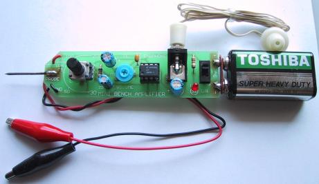
LM386 Audio Probe Amplifier |
|
LM386 audio probe amplifier is an essential tool for troubleshooting audio stages in audio related circuits such as amplifiers, oscillators, function generators, phone circuits, radios and lots of our other projects. It is a very handy piece of test equipment that can be built on pre-drilled board and will make a perfect addition to your electronic collection. There are lots of things that can go wrong with an audio stage. It can produce distortion or a “hollow” sound, go weak or simply fail altogether.
Likewise tone circuits can present a number of faults and it is very handy to be able to “hear” what is going wrong.
It is not sufficient to measure the DC voltages on these stages. This only gives a partial picture of the conditions and does not tell you the quality of the audio being processed. To determine this you need a piece of test equipment that will let you see or hear what is being processed. Some of the projects you can test with the Mini Bench Amplifier are tone circuits while others are audio circuits. Tone circuits and audio stages are surprisingly difficult to test unless you have an audio probe or a oscilloscope. Oscilloscope is an ideal piece of equipment but if your budget does not extend this far, the next best thing is an audio probe.
Firstly we will cover the benefits and problems of using a oscilloscope. The main problem with seeing the waveform on a oscilloscope is you have to interpret what you see and work out if distortion is present and where it is coming from. Believe me, this is harder to do than you think. Let me give some examples from a TV service-man friend. He has serviced some 35,000 TV sets over a period of 15 years and in that time he has used a oscilloscope on a number of occasions to try and find faults in audio stages.
One particularly troublesome audio fault occurred in an old black and white TV set, so he got out the oscilloscope to try and solve the problem.
The audio was weak and distorted but since the signals around IF transformers are very small even when the circuit is functioning correctly, he could not locate the fault.
Audio waveforms are seldom shown on circuit diagrams and it is difficult to know if the signal you are viewing on a oscilloscope is faulty or correct.
To fix the set he had to resort to the old tried-and-proven method of replacing components one-by-one. The fault turned out to be a 100p styro in one of the sound-IF cans. It had gone open-circuit and reduced the audio. But the oscilloscope didn't pick it up.
There were other occasions when he tried to use the oscilloscope but the result was the same. It didn't really help.
If you are a highly qualified audio technician and know the waveforms you should be getting at each location, it will be a completely different situation to trying to find an unknown fault in an audio stage. Sometimes an audio waveform is very messy when viewed on a oscilloscope and yet the audio is quite clean. Other times the waveform appears to be quite good and yet the signal is distorted.
If the oscilloscope was the answer to these problems, I would have no hesitation in suggesting you buy one, but it can sometimes create more problems than it solves.
To produce an audio waveform suitable for viewing on a oscilloscope, you have to inject the stage with a steady waveform such as from a function generator or sine-wave oscillator. You cannot simply supply it with a signal from a radio station as the signal will be varying in amplitude and changing in frequency. The oscilloscope will not be able to “lock in” and produce a stationary waveform.
You cannot work on a display that is constantly moving. This type of display is only suitable for amusement at a science exhibition. The screen must be perfectly stationary so you can view it and take measurements.
You need to measure the output and compare it to the input.
This is where a dual trace oscilloscope comes in handy. On this type of oscilloscope you will be able to display both the input and output at the same time and by super-imposing them on top of each other. You will then be able to see the differences.
Alternatively you can display one waveform above the other and pick out the differences.
If you only have a single trace oscilloscope, you will need to switch from the input to output as quickly as possible so the differences can be detected.
Even when you see a difference you will have to work out if it represents a fault.
An audio stage does not always produce distortion due to clipping or over-drive, it sometimes sounds `hollow' or `tinny' due to the coupling capacitors being too small or dried out. These types of faults will not be picked up on a oscilloscope and I suggest you save your money at this stage and build Audio Probe.
It will enable you fix audio faults very easily and save you a lot of frustration.
THE LM386
The LM386 is a high power op-amp. It is used to drive a speaker. The inverting input has been connected to the negative rail and the non-inverting input has been connected to a capacitor. Resistors inside the chip bias this input so that it only requires about 7mV before the chip turns on. This voltage is called the off-set voltage.
When a signal is applied to the “+” input, the chip amplifies the waveform and the result appears on pin 5. The gain of the chip depends on the impedance of the path between pins 1 and 8. We have placed a variable impedance, made up of a 22u and 10k pot between these pins and by varying the resistance of the pot, the gain of the chip will be adjusted.
The gain can be adjusted from 30 to 200 and these figures are shown on the overlay of the board.
FIXING AUDIO STAGES
As we said, there can be lots of problems with audio stages. Sometimes they develop over a period of time, or they can be present from the moment the amplifier is assembled. You can also get intermittent faults, drop outs, squealing, motor-boating, distortion or simply lack of gain.
The amplifier presented in this article is used as an audio probe by listening to the loudness and quality of the audio going into the stage under test and comparing it to the audio emerging from the output of the stage.
You do this by putting the earpiece near your ear and listening carefully - that's why the probe has two long leads.
We could write a book on fixing audio stages but to reduce it to one page, here is the approach:
The simplest situation is a single transistor amplifier with a distorted output.
The first thing to do is replace the transistor. Even though transistors are very reliable devices, you may have overheated it and this will cause the device to have a different gain and thus the voltages on the stage will not allow the signal to be processed correctly (you can put it back later if it is not the cause of the problem).
The next thing is measure the voltage on the collector. Ideally it should be half-rail. This allows the transistor to turn on and off THE MAXIMUM AMOUNT and thus give the stage the maximum gain.
To carry out any more investigation on the stage you will need a copy of the circuit diagram. This will let you know how the transistor is biased and may give details of the voltages at the various locations.
Next look at the electrolytics. These can be inter-stage devices, decoupling or emitter bypass capacitors. They can dry-out and lose their capacitance or go open (very rarely) or go short-circuit (very rare). Tantalums can also go short-circuit as they are susceptible to high voltage spikes that puncture their ceramic substrate.
If the transistor has an emitter by-pass capacitor in the form of an electrolytic aoscilloscopess the emitter resistor, the stage gain will be severely reduced if the capacitor (electrolytic) has lost its capacitance (dried out).
A faulty inter-stage capacitor (one that connects the output of one stage to the input of the next) can be checked by placing the probe one side of the capacitor, then the other. If the audio level drops considerably, the capacitor is not passing the signal and may be faulty.
If you have replaced the transistor with another type, the voltage on the collector may be different to that specified.
If it is lower, the transistor has a higher gain and the base-bias resistor must be increased. If it is higher than expected, the base-bias resistor must be decreased.
This only applies to simple self-biasing stages, where the base-bias resistor sets the collector voltage for the stage.
Resistors rarely give trouble except if they are of an old style or in a position where they get hot.
If hum is present on the audio, the fault will lie in the filtering of the power supply. If a squeal similar to a feed-back squeal, (as heard when a mioscilloscopephone is too near the speaker of an amplifier), the fault can be in the decoupling capacitor. This is generally a small value electrolytic (10u to 100u) near the stage it is protecting and will be associated with a low value resistor on the power rail. The electrolytic is connected aoscilloscopess the power rails.
This electrolytic can also produce a fault similar to the putt-putt-putt of a motor boat exhaust system, bubbling through water.
Probe amplifier has a volume control in the form of a gain control, to vary the output volume from the earpiece. The approximate gain is marked around the control.
An additional probe can be connected to the board via a small socket and this will allow the Mini Amplifier to be brought up to your ear so you can listen to the audio.
IF IT DOESN'T WORK
Switch the Audio Probe on and turn the gain control to maximum. Touch the active probe with your finger. You should hear a slight buzz from the speaker. This is a quick test to show the project is working. If nothing is detected, you should follow these steps:
If the power LED doesn't come on, the most probable cause is a flat battery or the battery terminals not making contact.
Also check the placement of the LED as it may be around the wrong way.
Next check the current taken by the circuit, across the switch (with the switch in the OFF position). It should be about 10mA.
If no sound comes from the earpiece, measure its resistance with a multimeter. It should produce a slight `click' when you do this and measure about 8 ohms.
Check that pin 1 of the IC is near the cut-out on the overlay and see that all the pins of the chip are entering the socket. Sometimes a pin bends over and does not make contact. Also make sure all the pins of the socket are soldered to the board. This applies to all the other components. Finally, make sure the positive of the battery goes to the positive rail on the board and the negative goes to the negative rail.
There is little else that can go wrong and the project should be working by now.
USING AUDIO PROBE
All you have to do is connect the ground lead to the project you are testing, switch the Audio Probe on and also the project you are testing. Use the probe or the active lead to probe various points on the project under test and listen for the audio. The gain control on the Audio Probe is very similar to a volume control and will allow you to hear the audio without too much over-drive.
Most amplifying stages have a gain of about 50 - 70. Some will have a gain of about 100 but this is about as high as you will get.
It is impossible to describe how to determine if a stage has high or low gain, merely by listening to it. The only way to work out a gain factor is to use a CRO.
One clever way to fault-find a project is to get another identical unit and compare one with the other.
To do this you need to set both beside each other and join the ground lines together. Turn them both ON and you can then probe each stage and compare one with the other.
If you have had the frustration of trying to diagnose an audio stage, you will find this project absolutely essential.
Related Links
Downloads
LM386 Audio Probe Amplifier - Link
|
|
|
| |
Accurate LC Meter
Build your own Accurate LC Meter (Capacitance Inductance Meter) and start making your own coils and inductors. This LC Meter allows to measure incredibly small inductances making it perfect tool for making all types of RF coils and inductors. LC Meter can measure inductances starting from 10nH - 1000nH, 1uH - 1000uH, 1mH - 100mH and capacitances from 0.1pF up to 900nF. The circuit includes an auto ranging as well as reset switch and produces very accurate and stable readings. |
|
PIC Volt Ampere Meter
Volt Ampere Meter measures voltage of 0-70V or 0-500V with 100mV resolution and current consumption 0-10A or more with 10mA resolution. The meter is a perfect addition to any power supply, battery chargers and other electronic projects where voltage and current must be monitored. The meter uses PIC16F876A microcontroller with 16x2 backlighted LCD. |
|
|
|
60MHz Frequency Meter / Counter
Frequency Meter / Counter measures frequency from 10Hz to 60MHz with 10Hz resolution. It is a very useful bench test equipment for testing and finding out the frequency of various devices with unknown frequency such as oscillators, radio receivers, transmitters, function generators, crystals, etc. |
|
1Hz - 2MHz XR2206 Function Generator
1Hz - 2MHz XR2206 Function Generator produces high quality sine, square and triangle waveforms of high-stability and accuracy. The output waveforms can be both amplitude and frequency modulated. Output of 1Hz - 2MHz XR2206 Function Generator can be connected directly to 60MHz Counter for setting precise frequency output. |
|
|
|
BA1404 HI-FI Stereo FM Transmitter
Be "On Air" with your own radio station! BA1404 HI-FI Stereo FM Transmitter broadcasts high quality stereo signal in 88MHz - 108MHz FM band. It can be connected to any type of stereo audio source such as iPod, Computer, Laptop, CD Player, Walkman, Television, Satellite Receiver, Tape Deck or other stereo system to transmit stereo sound with excellent clarity throughout your home, office, yard or camp ground. |
|
USB IO Board
USB IO Board is a tiny spectacular little development board / parallel port replacement featuring PIC18F2455/PIC18F2550 microcontroller. USB IO Board is compatible with Windows / Mac OSX / Linux computers. When attached to Windows IO board will show up as RS232 COM port. You can control 16 individual microcontroller I/O pins by sending simple serial commands. USB IO Board is self-powered by USB port and can provide up to 500mA for electronic projects. USB IO Board is breadboard compatible. |
|
|
|
|
ESR Meter / Capacitance / Inductance / Transistor Tester Kit
ESR Meter kit is an amazing multimeter that measures ESR values, capacitance (100pF - 20,000uF), inductance, resistance (0.1 Ohm - 20 MOhm), tests many different types of transistors such as NPN, PNP, FETs, MOSFETs, Thyristors, SCRs, Triacs and many types of diodes. It also analyzes transistor's characteristics such as voltage and gain. It is an irreplaceable tool for troubleshooting and repairing electronic equipment by determining performance and health of electrolytic capacitors. Unlike other ESR Meters that only measure ESR value this one measures capacitor's ESR value as well as its capacitance all at the same time. |
|
Audiophile Headphone Amplifier Kit
Audiophile headphone amplifier kit includes high quality audio grade components such as Burr Brown OPA2134 opamp, ALPS volume control potentiometer, Ti TLE2426 rail splitter, Ultra-Low ESR 220uF/25V Panasonic FM filtering capacitors, High quality WIMA input and decoupling capacitors and Vishay Dale resistors. 8-DIP machined IC socket allows to swap OPA2134 with many other dual opamp chips such as OPA2132, OPA2227, OPA2228, dual OPA132, OPA627, etc. Headphone amplifier is small enough to fit in Altoids tin box, and thanks to low power consumption may be supplied from a single 9V battery. |
|
|
|
|
|
Arduino Prototype Kit
Arduino Prototype is a spectacular development board fully compatible with Arduino Pro. It's breadboard compatible so it can be plugged into a breadboard for quick prototyping, and it has VCC & GND power pins available on both sides of PCB. It's small, power efficient, yet customizable through onboard 2 x 7 perfboard that can be used for connecting various sensors and connectors. Arduino Prototype uses all standard through-hole components for easy construction, two of which are hidden underneath IC socket. Board features 28-PIN DIP IC socket, user replaceable ATmega328 microcontroller flashed with Arduino bootloader, 16MHz crystal resonator and a reset switch. It has 14 digital input/output pins (0-13) of which 6 can be used as PWM outputs and 6 analog inputs (A0-A5). Arduino sketches are uploaded through any USB-Serial adapter connected to 6-PIN ICSP female header. Board is supplied by 2-5V voltage and may be powered by a battery such as Lithium Ion cell, two AA cells, external power supply or USB power adapter. |
|
200m 4-Channel 433MHz Wireless RF Remote Control
Having the ability to control various appliances inside or outside of your house wirelessly is a huge convenience, and can make your life much easier and fun. RF remote control provides long range of up to 200m / 650ft and can find many uses for controlling different devices, and it works even through the walls. You can control lights, fans, AC system, computer, printer, amplifier, robots, garage door, security systems, motor-driven curtains, motorized window blinds, door locks, sprinklers, motorized projection screens and anything else you can think of. |
|
|
|