| |
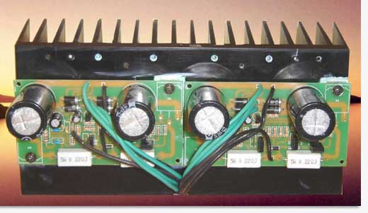
100W HI-FI MOSFET Amplifier |
|
Here is a simple 100W HI-FI MOSFET Amplifier.
The main feature of this amplifier is a simple design and assembly. Simplicity of the circuit by looking at the circuit you expect amplifier to be simple. It should be noted that many hi-end amplifiers have a very simple but good quality designs. General technological theory is due to fewer parts, fewer problems. Additionally power to supplement your system is quite effective. Power supply transformer is very important. 8 Ohm output for a 35 - 0 to 35 V and at least 3 amps per power amplifier is recommended that a transformer can be transferred. Naturally, the two substations will be required for stereo use.

Straightening 3A diodes bridge circuit is connected to.
The circuit is located on the 2 x 4700μF 63v capacitor filter hood. This power supply circuit for a single channel and two channels and two transformers to be installed in two separate feed circuit. However, if you use the one constant in this amplifier 5A transformer may be sufficient.
The circuit is very simple. MPSA56 (= BC556) s differential input pair, BD139 and BD140 s pairs in the current drive. These transistors have been selected because of the quality of sound as a result of long experience.
The complementary pairs of output transistors Hitachi 2SK1058 and 2SJ162 MOSFET'leridir conjugate. These are some expensive transistörlerdir (10 €), but none of equivalents do not recommend it because it is not for audio applications. The gate voltage of MOSFETs, and this limitation has diyotlarına provide some fault tolerance and protection. However, for a better protection to the speaker I would recommend to add insurance 3A slow. * (1)
One advantage of using the MOSFET output stage; secondary crash (secondary breakdown) is not stable, and all kinds of amplifier remains at ambient temperature. Serenity of the circuit current is around 210mA. This is because the circuit to the level of approximately 8W Class A Class B is passed to work after that. As a result, the average listening on a very low distortion is provided.
Simple design of a printed circuit board designed to connect to the four mounting holes and added directly to the cooler. MOSFETs also facilitate the work of the PCB assembly will be toast from the refrigerator, compact, solidly built and will have a design for an amplifier transistor, which is a big advantage.
Input / outputs if the future .. Signal input of J1, J2 signal chassis. Speakers connected between J3 J7. 35V Transformer in connection J6, 0 J4, J5 will be as if the other 35V.
Amp also has a modular structure, prompted a bridge connecting two 8 ohm load, 250W RMS power amplifier can be configured to convey. For this, the first amplifier input signal is connected to J1 and J2, J1 and J2 s second amplifkatörün by a short circuit, the first, second amplinin J8 J3 tip connected to the speaker output. In this case, two amplifier's speaker output terminals to be connected J3'lerinden to be taken, and J7.
While there is a deterioration in the bridge mode, no sound study, up to 16W of class A must not forget that run. However, you must not forget that this is a bridge amplifier and 300W continuous power output of at least one speaker connected to the handle. In this case, it is useful to choose the output fuse 8A.
Amplifier designed and ran a lot of about 40 years. I saw that the very high quality filter capacitors with low equivalent resistance as a result, constitute a change in sound quality. For example, you can try to see Nichion Gold series, but you get better quality results in a capacitor or Hitano'dan Rubicon will not be different.
Note:
Directly to the output transistors of the circuit under pressure vidalanacaktır cooler. Therefore, this process will be fixed when the printed circuit board. Insulator and silicon grease between the cooler transistors must be banished. Otherwise you will short circuit the supply terminals.
CN: * (1) transistor amplifiers as a general rule, there is no protection circuitry. This circuit is the need to protect the output against excessive movements and as well as not have DC'e.
CN1: This application is definitely not suitable for beginners. Friends, I would recommend starting a new project in the No. 1.
Component List
Taylor 0R22 5.0W Resistor (R19, R25) 2 Units
1K0 0.25W 5% resistor (R9, R10) 2 Units
1K2 0.25W 5% resistor (R14) 1 Piece
1N4148 diode (D1, D2) 2 Units
1N5404 diode (D3, D4, D5, D6) 4 Units
2K2 0.25W 5% resistor (R23) 1 Piece
Power MOSFET 2SJ162 (TO3P sheath) (Q3) 1 Piece
2SK1058 Power MOSFET (TO3P sheath) (Q5) 1 Piece
3K9 0.25W 5% resistor (R12, R13) 2 Units
10R 1.0W 5% (R24) 1 Piece
10K 0.25W 5% (R8) 1 Piece
10u 16V capacitor (C1) 1 Piece
47k 0.25W 5% resistor (R2, R3, R15, R16) 4 Units
Capacitor 47U 35V 8mm (C2) 1 Piece
82P 50V 5mm Ceramic Disc Capacitor (C5, C6) 2 Units
100N 50V Ceramic Disc Capacitor (C3, C7) 2 Units
470R 0.25W 5% resistor (R5, R6) 2 Units
470P/50V 5mm Ceramic Disc Capacitors (C4) 1 Piece
4700u 25mm 63V Radial Capacitor (C8, C9) 2 Units
Transistor BD139 TO 225 (Q9, Q10) 2 Units
Transistor BD140 TO 225 (Q7, Q8) 2 Units
Transistor MPSA56 TO 92 (Q1, Q12) 2 Units
Transformer 40V - 0 - 40V 3 A 1 Piece

Related Links
Downloads
100W HI-FI MOSFET Amplifier - Link
|
|
|
| |
Accurate LC Meter
Build your own Accurate LC Meter (Capacitance Inductance Meter) and start making your own coils and inductors. This LC Meter allows to measure incredibly small inductances making it perfect tool for making all types of RF coils and inductors. LC Meter can measure inductances starting from 10nH - 1000nH, 1uH - 1000uH, 1mH - 100mH and capacitances from 0.1pF up to 900nF. The circuit includes an auto ranging as well as reset switch and produces very accurate and stable readings. |
|
PIC Volt Ampere Meter
Volt Ampere Meter measures voltage of 0-70V or 0-500V with 100mV resolution and current consumption 0-10A or more with 10mA resolution. The meter is a perfect addition to any power supply, battery chargers and other electronic projects where voltage and current must be monitored. The meter uses PIC16F876A microcontroller with 16x2 backlighted LCD. |
|
|
|
60MHz Frequency Meter / Counter
Frequency Meter / Counter measures frequency from 10Hz to 60MHz with 10Hz resolution. It is a very useful bench test equipment for testing and finding out the frequency of various devices with unknown frequency such as oscillators, radio receivers, transmitters, function generators, crystals, etc. |
|
1Hz - 2MHz XR2206 Function Generator
1Hz - 2MHz XR2206 Function Generator produces high quality sine, square and triangle waveforms of high-stability and accuracy. The output waveforms can be both amplitude and frequency modulated. Output of 1Hz - 2MHz XR2206 Function Generator can be connected directly to 60MHz Counter for setting precise frequency output. |
|
|
|
BA1404 HI-FI Stereo FM Transmitter
Be "On Air" with your own radio station! BA1404 HI-FI Stereo FM Transmitter broadcasts high quality stereo signal in 88MHz - 108MHz FM band. It can be connected to any type of stereo audio source such as iPod, Computer, Laptop, CD Player, Walkman, Television, Satellite Receiver, Tape Deck or other stereo system to transmit stereo sound with excellent clarity throughout your home, office, yard or camp ground. |
|
USB IO Board
USB IO Board is a tiny spectacular little development board / parallel port replacement featuring PIC18F2455/PIC18F2550 microcontroller. USB IO Board is compatible with Windows / Mac OSX / Linux computers. When attached to Windows IO board will show up as RS232 COM port. You can control 16 individual microcontroller I/O pins by sending simple serial commands. USB IO Board is self-powered by USB port and can provide up to 500mA for electronic projects. USB IO Board is breadboard compatible. |
|
|
|
|
ESR Meter / Capacitance / Inductance / Transistor Tester Kit
ESR Meter kit is an amazing multimeter that measures ESR values, capacitance (100pF - 20,000uF), inductance, resistance (0.1 Ohm - 20 MOhm), tests many different types of transistors such as NPN, PNP, FETs, MOSFETs, Thyristors, SCRs, Triacs and many types of diodes. It also analyzes transistor's characteristics such as voltage and gain. It is an irreplaceable tool for troubleshooting and repairing electronic equipment by determining performance and health of electrolytic capacitors. Unlike other ESR Meters that only measure ESR value this one measures capacitor's ESR value as well as its capacitance all at the same time. |
|
Audiophile Headphone Amplifier Kit
Audiophile headphone amplifier kit includes high quality audio grade components such as Burr Brown OPA2134 opamp, ALPS volume control potentiometer, Ti TLE2426 rail splitter, Ultra-Low ESR 220uF/25V Panasonic FM filtering capacitors, High quality WIMA input and decoupling capacitors and Vishay Dale resistors. 8-DIP machined IC socket allows to swap OPA2134 with many other dual opamp chips such as OPA2132, OPA2227, OPA2228, dual OPA132, OPA627, etc. Headphone amplifier is small enough to fit in Altoids tin box, and thanks to low power consumption may be supplied from a single 9V battery. |
|
|
|
|
|
Arduino Prototype Kit
Arduino Prototype is a spectacular development board fully compatible with Arduino Pro. It's breadboard compatible so it can be plugged into a breadboard for quick prototyping, and it has VCC & GND power pins available on both sides of PCB. It's small, power efficient, yet customizable through onboard 2 x 7 perfboard that can be used for connecting various sensors and connectors. Arduino Prototype uses all standard through-hole components for easy construction, two of which are hidden underneath IC socket. Board features 28-PIN DIP IC socket, user replaceable ATmega328 microcontroller flashed with Arduino bootloader, 16MHz crystal resonator and a reset switch. It has 14 digital input/output pins (0-13) of which 6 can be used as PWM outputs and 6 analog inputs (A0-A5). Arduino sketches are uploaded through any USB-Serial adapter connected to 6-PIN ICSP female header. Board is supplied by 2-5V voltage and may be powered by a battery such as Lithium Ion cell, two AA cells, external power supply or USB power adapter. |
|
200m 4-Channel 433MHz Wireless RF Remote Control
Having the ability to control various appliances inside or outside of your house wirelessly is a huge convenience, and can make your life much easier and fun. RF remote control provides long range of up to 200m / 650ft and can find many uses for controlling different devices, and it works even through the walls. You can control lights, fans, AC system, computer, printer, amplifier, robots, garage door, security systems, motor-driven curtains, motorized window blinds, door locks, sprinklers, motorized projection screens and anything else you can think of. |
|
|
|