| |
There are many types of power supply. Most are designed to convert high voltage AC mains electricity to a suitable low voltage supply for electronics circuits and other devices. A power supply can by broken down into a series of blocks, each of which performs a particular function. Each of the blocks is described in more detail below:
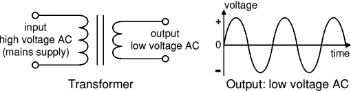
Transformer - steps down high voltage AC mains to low voltage AC.
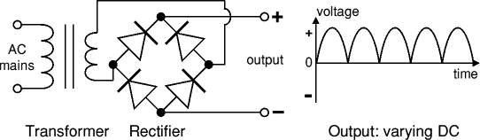
Rectifier - converts AC to DC, but the DC output is varying.
Smoothing - smooths the DC from varying greatly to a small ripple.
Regulator - eliminates ripple by setting DC output to a fixed voltage.
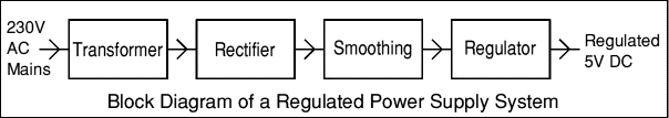
Power supplies made from these blocks are described below with a circuit diagram and a graph of their output:
Transformer only
Transformer + Rectifier
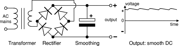
Transformer + Rectifier + Smoothing
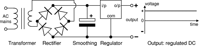
Transformer + Rectifier + Smoothing + Regulator
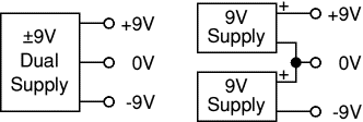
Dual Supplies
Dual power supply Some electronic circuits require a power supply with positive and negative outputs as well as zero volts (0V). This is called a 'dual supply' because it is like two ordinary supplies connected together as shown in the diagram.
Dual supplies have three outputs, for example a ±9V supply has +9V, 0V and -9V outputs.
Transformer only
AC power supply, transformer only
The low voltage AC output is suitable for lamps, heaters and special AC motors. It is not suitable for electronic circuits unless they include a rectifier and a smoothing capacitor.
Further information: Transformer
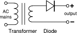
Transformer + Rectifier
DC power supply, transformer + rectifier
The varying DC output is suitable for lamps, heaters and standard motors. It is not suitable for electronic circuits unless they include a smoothing capacitor.
Further information: Transformer | Rectifier
Transformer + Rectifier + Smoothing
Smooth DC power supply, transformer + rectifier + smoothing
The smooth DC output has a small ripple. It is suitable for most electronic circuits.
Further information: Transformer | Rectifier | Smoothing
Transformer + Rectifier + Smoothing + Regulator
Regulated DC power supply, transformer + rectifier + smoothing + regulator
The regulated DC output is very smooth with no ripple. It is suitable for all electronic circuits.
Further information: Transformer | Rectifier | Smoothing | Regulator
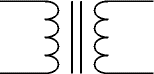
Transformer
transformer symbol
Transformer
circuit symbol
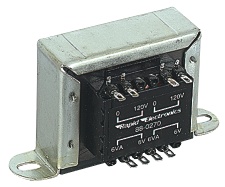
Transformer, photograph © Rapid Electronics
Transformer
Photograph © Rapid Electronics
There is more information
about transformers on the
Electronics in Meccano
website.
Transformers convert AC electricity from one voltage to another with little loss of power. Transformers work only with AC and this is one of the reasons why mains electricity is AC.
Step-up transformers increase voltage, step-down transformers reduce voltage. Most power supplies use a step-down transformer to reduce the dangerously high mains voltage (230V in UK) to a safer low voltage.
The input coil is called the primary and the output coil is called the secondary. There is no electrical connection between the two coils, instead they are linked by an alternating magnetic field created in the soft-iron core of the transformer. The two lines in the middle of the circuit symbol represent the core.
Transformers waste very little power so the power out is (almost) equal to the power in. Note that as voltage is stepped down current is stepped up.
The ratio of the number of turns on each coil, called the turns ratio, determines the ratio of the voltages. A step-down transformer has a large number of turns on its primary (input) coil which is connected to the high voltage mains supply, and a small number of turns on its secondary (output) coil to give a low output voltage.
turns ratio = Vp = Np and power out = power in
Vs Ns Vs × Is = Vp × Ip
Vp = primary (input) voltage
Np = number of turns on primary coil
Ip = primary (input) current Vs = secondary (output) voltage
Ns = number of turns on secondary coil
Is = secondary (output) current
Rectifier
There is more information
about rectifiers on the
Electronics in Meccano
website.
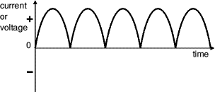
There are several ways of connecting diodes to make a rectifier to convert AC to DC. The bridge rectifier is the most important and it produces full-wave varying DC. A full-wave rectifier can also be made from just two diodes if a centre-tap transformer is used, but this method is rarely used now that diodes are cheaper. A single diode can be used as a rectifier but it only uses the positive (+) parts of the AC wave to produce half-wave varying DC.
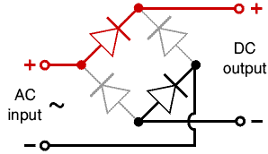
Bridge rectifier
A bridge rectifier can be made using four individual diodes, but it is also available in special packages containing the four diodes required. It is called a full-wave rectifier because it uses all the AC wave (both positive and negative sections). 1.4V is used up in the bridge rectifier because each diode uses 0.7V when conducting and there are always two diodes conducting, as shown in the diagram below. Bridge rectifiers are rated by the maximum current they can pass and the maximum reverse voltage they can withstand (this must be at least three times the supply RMS voltage so the rectifier can withstand the peak voltages). Please see the Diodes page for more details, including pictures of bridge rectifiers.
Operation of a Bridge Rectifier Full-wave Varying DC
Bridge rectifier
Alternate pairs of diodes conduct, changing over
the connections so the alternating directions of
AC are converted to the one direction of DC. Output: full-wave varying DC
(using all the AC wave)
Single diode rectifier
A single diode can be used as a rectifier but this produces half-wave varying DC which has gaps when the AC is negative. It is hard to smooth this sufficiently well to supply electronic circuits unless they require a very small current so the smoothing capacitor does not significantly discharge during the gaps. Please see the Diodes page for some examples of rectifier diodes.
Single diode rectifier Half-wave Varying DC
Single diode rectifier Output: half-wave varying DC
(using only half the AC wave)
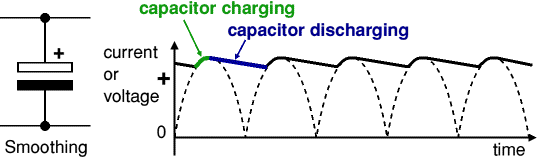
Smoothing
Smoothing is performed by a large value electrolytic capacitor connected across the DC supply to act as a reservoir, supplying current to the output when the varying DC voltage from the rectifier is falling. The diagram shows the unsmoothed varying DC (dotted line) and the smoothed DC (solid line). The capacitor charges quickly near the peak of the varying DC, and then discharges as it supplies current to the output.
Smoothing
Note that smoothing significantly increases the average DC voltage to almost the peak value (1.4 × RMS value). For example 6V RMS AC is rectified to full wave DC of about 4.6V RMS (1.4V is lost in the bridge rectifier), with smoothing this increases to almost the peak value giving 1.4 × 4.6 = 6.4V smooth DC.
Smoothing is not perfect due to the capacitor voltage falling a little as it discharges, giving a small ripple voltage. For many circuits a ripple which is 10% of the supply voltage is satisfactory and the equation below gives the required value for the smoothing capacitor. A larger capacitor will give less ripple. The capacitor value must be doubled when smoothing half-wave DC.
There is more information
about smoothing on the
Electronics in Meccano
website.
Smoothing capacitor for 10% ripple, C = 5 × Io
Vs × f
C = smoothing capacitance in farads (F)
Io = output current from the supply in amps (A)
Vs = supply voltage in volts (V), this is the peak value of the unsmoothed DC
f = frequency of the AC supply in hertz (Hz), 50Hz in the UK
Regulator
Voltage regulator Voltage regulator, photograph © Rapid Electronics
Voltage regulator
Photograph © Rapid Electronics
Voltage regulator ICs are available with fixed (typically 5, 12 and 15V) or variable output voltages. They are also rated by the maximum current they can pass. Negative voltage regulators are available, mainly for use in dual supplies. Most regulators include some automatic protection from excessive current ('overload protection') and overheating ('thermal protection').
Many of the fixed voltage regulator ICs have 3 leads and look like power transistors, such as the 7805 +5V 1A regulator shown on the right. They include a hole for attaching a heatsink if necessary.
Please see the Electronics in Meccano website for more information about voltage regulator ICs.
Zener diode
zener diode
a = anode, k = cathode
Zener diode circuit
Zener diode regulator
For low current power supplies a simple voltage regulator can be made with a resistor and a zener diode connected in reverse as shown in the diagram. Zener diodes are rated by their breakdown voltage Vz and maximum power Pz (typically 400mW or 1.3W).
The resistor limits the current (like an LED resistor). The current through the resistor is constant, so when there is no output current all the current flows through the zener diode and its power rating Pz must be large enough to withstand this.
Please see the Diodes page for more information about zener diodes.
Choosing a zener diode and resistor:
The zener voltage Vz is the output voltage required
The input voltage Vs must be a few volts greater than Vz
(this is to allow for small fluctuations in Vs due to ripple)
The maximum current Imax is the output current required plus 10%
The zener power Pz is determined by the maximum current: Pz > Vz × Imax
The resistor resistance: R = (Vs - Vz) / Imax
The resistor power rating: P > (Vs - Vz) × Imax
Example: output voltage required is 5V, output current required is 60mA.
There is more information
about regulators on the
Electronics in Meccano
website.
Vz = 4.7V (nearest value available)
Vs = 8V (it must be a few volts greater than Vz)
Imax = 66mA (output current plus 10%)
Pz > 4.7V × 66mA = 310mW, choose Pz = 400mW
R = (8V - 4.7V) / 66mA = 0.05kohm = 50ohm, choose R = 47ohm
Resistor power rating P > (8V - 4.7V) × 66mA = 218mW, choose P = 0.5W
|
|
|
| |
Accurate LC Meter
Build your own Accurate LC Meter (Capacitance Inductance Meter) and start making your own coils and inductors. This LC Meter allows to measure incredibly small inductances making it perfect tool for making all types of RF coils and inductors. LC Meter can measure inductances starting from 10nH - 1000nH, 1uH - 1000uH, 1mH - 100mH and capacitances from 0.1pF up to 900nF. The circuit includes an auto ranging as well as reset switch and produces very accurate and stable readings. |
|
PIC Volt Ampere Meter
Volt Ampere Meter measures voltage of 0-70V or 0-500V with 100mV resolution and current consumption 0-10A or more with 10mA resolution. The meter is a perfect addition to any power supply, battery chargers and other electronic projects where voltage and current must be monitored. The meter uses PIC16F876A microcontroller with 16x2 backlighted LCD. |
|
|
|
60MHz Frequency Meter / Counter
Frequency Meter / Counter measures frequency from 10Hz to 60MHz with 10Hz resolution. It is a very useful bench test equipment for testing and finding out the frequency of various devices with unknown frequency such as oscillators, radio receivers, transmitters, function generators, crystals, etc. |
|
1Hz - 2MHz XR2206 Function Generator
1Hz - 2MHz XR2206 Function Generator produces high quality sine, square and triangle waveforms of high-stability and accuracy. The output waveforms can be both amplitude and frequency modulated. Output of 1Hz - 2MHz XR2206 Function Generator can be connected directly to 60MHz Counter for setting precise frequency output. |
|
|
|
BA1404 HI-FI Stereo FM Transmitter
Be "On Air" with your own radio station! BA1404 HI-FI Stereo FM Transmitter broadcasts high quality stereo signal in 88MHz - 108MHz FM band. It can be connected to any type of stereo audio source such as iPod, Computer, Laptop, CD Player, Walkman, Television, Satellite Receiver, Tape Deck or other stereo system to transmit stereo sound with excellent clarity throughout your home, office, yard or camp ground. |
|
USB IO Board
USB IO Board is a tiny spectacular little development board / parallel port replacement featuring PIC18F2455/PIC18F2550 microcontroller. USB IO Board is compatible with Windows / Mac OSX / Linux computers. When attached to Windows IO board will show up as RS232 COM port. You can control 16 individual microcontroller I/O pins by sending simple serial commands. USB IO Board is self-powered by USB port and can provide up to 500mA for electronic projects. USB IO Board is breadboard compatible. |
|
|
|
|
ESR Meter / Capacitance / Inductance / Transistor Tester Kit
ESR Meter kit is an amazing multimeter that measures ESR values, capacitance (100pF - 20,000uF), inductance, resistance (0.1 Ohm - 20 MOhm), tests many different types of transistors such as NPN, PNP, FETs, MOSFETs, Thyristors, SCRs, Triacs and many types of diodes. It also analyzes transistor's characteristics such as voltage and gain. It is an irreplaceable tool for troubleshooting and repairing electronic equipment by determining performance and health of electrolytic capacitors. Unlike other ESR Meters that only measure ESR value this one measures capacitor's ESR value as well as its capacitance all at the same time. |
|
Audiophile Headphone Amplifier Kit
Audiophile headphone amplifier kit includes high quality audio grade components such as Burr Brown OPA2134 opamp, ALPS volume control potentiometer, Ti TLE2426 rail splitter, Ultra-Low ESR 220uF/25V Panasonic FM filtering capacitors, High quality WIMA input and decoupling capacitors and Vishay Dale resistors. 8-DIP machined IC socket allows to swap OPA2134 with many other dual opamp chips such as OPA2132, OPA2227, OPA2228, dual OPA132, OPA627, etc. Headphone amplifier is small enough to fit in Altoids tin box, and thanks to low power consumption may be supplied from a single 9V battery. |
|
|
|
|
|
Arduino Prototype Kit
Arduino Prototype is a spectacular development board fully compatible with Arduino Pro. It's breadboard compatible so it can be plugged into a breadboard for quick prototyping, and it has VCC & GND power pins available on both sides of PCB. It's small, power efficient, yet customizable through onboard 2 x 7 perfboard that can be used for connecting various sensors and connectors. Arduino Prototype uses all standard through-hole components for easy construction, two of which are hidden underneath IC socket. Board features 28-PIN DIP IC socket, user replaceable ATmega328 microcontroller flashed with Arduino bootloader, 16MHz crystal resonator and a reset switch. It has 14 digital input/output pins (0-13) of which 6 can be used as PWM outputs and 6 analog inputs (A0-A5). Arduino sketches are uploaded through any USB-Serial adapter connected to 6-PIN ICSP female header. Board is supplied by 2-5V voltage and may be powered by a battery such as Lithium Ion cell, two AA cells, external power supply or USB power adapter. |
|
200m 4-Channel 433MHz Wireless RF Remote Control
Having the ability to control various appliances inside or outside of your house wirelessly is a huge convenience, and can make your life much easier and fun. RF remote control provides long range of up to 200m / 650ft and can find many uses for controlling different devices, and it works even through the walls. You can control lights, fans, AC system, computer, printer, amplifier, robots, garage door, security systems, motor-driven curtains, motorized window blinds, door locks, sprinklers, motorized projection screens and anything else you can think of. |
|
|
|


