| |
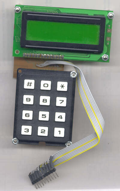
0 - 5V PIC voltmeter circuit consists only of a PIC16F876 (or other 16F87x), a 10-MHz oscillator and a dot-matrix displa y. The analog voltage is fed to the PIC RA0 ind. To show the 10 Bittig measured ADC value is 4 digits on the LCD shown in decimal (in millivolts).
An analog input voltage of 0V ... 5V is measured and displayed on the LCD. The voltage measurement and the binary indicator was discussed.
The control of an LCD are not new.
If, however, the voltage measured in volts or millivolts on the LCD display, a little 'data processing' is necessary.
Circuit
The circuit consists only of a PIC16F876 (or other 16F87x), a 10-MHz oscillator and a dot-matrix displa y. The analog voltage is fed to the PIC RA0 ind.
To show the 10 Bittig measured ADC value is 4 digits on the LCD shown in decimal (in millivolts).
For example, the building is suitable 16F876-board test . and the LCD adapter board .
When burning the PIC is the HS oscillator select
+ + WARNING + +
to the PIC not to damage, should the input voltage at RA0 pin is not less than Vpp-0, 3V or greater than Vdd +0.3 V! Who can not guarantee should input with a resistor and two protection diodes (Schottky diodes to Vdd and Vss) protect, such as for example in simple ADC sample is to be seen.
Problem No. 1
Is Vdd (+5 V) is used as a reference voltage, the ADC measured with a resolution of 5V / 1024 = 4.8828125 mV.
The binary 10-bit A / D conversion result (U adc ) can be converted to a millivolt value in, if it is multiplied by 4.8828125.
U [mV] = 4.8828125 * Uadc
This corresponds to a multiplication by 5 and a subsequent division by 1.024 .
How can we solve this problem without having to operate a real floating-point math?
In a PIC can easily perform the following calculations:
Addition ( ADDWF )
Subtraction ( SUBWF )
Multiplying by 2 ( RLF ), minimum
Division by 2 ( RRF ), halving
The commands are in parentheses next to the operations. Which is really only 8-bit operations can be relatively easily expanded simply to 16 bits. These 16 bits are sufficient to handle our ADC results (10 bit).
The above required multiplication by 5 to 2 can be easily implemented ways.
The number is added to itself 4 times
The number is doubled 2 times, this is again the number added to itself
The division by 1.024 is somewhat difficult. The same goes,
X / X = 1.024 - X/64 - X/128
This results, therefore, the voltage in millivolts following calculation method:
U [mV] = 5Uadc - 5Uadc/64 - 5Uadc/128
This calculation is easy to Bitverschiebebefehle, a 16-bit addition and subtraction, two 16-bit back to them. To right multiplication and division can give themselves.
Problem No. 2
We now have the voltage at pin RA0 in millivolts determined. Our number is still a binary number. The LCD display we wish to display a decimal number. These binary-to-decimal conversion is necessary.
To convert a binary number to a decimal number, there are two possibilities
Repeated Division by Ten
Repeated subtraction by orders of magnitude.
Also a division by 10 can be killed with the subtraction. Man is trying just as often can be subtracted from a number, without obtaining a negative result.
Way to solve: 16-bit addition / subtraction
What we need in all circumstances the 16-bit addition, and the 16-bit subtraction. Both need one small subroutine. Since all the registers of the PIC is only 8 bits are great, I put each down two registers to store each composed a 16-bit number:
f1 f0 together and save 16-bit, with the high part (Bit8. .15) in f1 and the low part (Bit0. .7) is stored in f0.
XW1 xw0 together and save 16-bit, with the high part (Bit8. .15) in XW1 and the low part (Bit0. .7) is stored in xw0.
The choice of name and xw f is completely arbitrary. must of course f0, f1, xw0 XW1 and have a promise with equ statements real registers.
16 bit addition
Following code shows a 16-bit addition of the values f (f1, f0) and xw (XW1, xw0). The 16-bit result is stored in f, xw is not changed. If the Ergebins 17 bits in size, so as a sign of the overflow, the C bit in the STATUS register ..
;************************************************* ********************
, 16 bit Adition, C flag is set on overflow
Add16, 16-bit add: f: = f + xw
movf xw0, W; xw0 to W
addwf f0, F; f0 = f0 + xw0
movf XW1, W; XW1 to W
btfsc STATUS, C; case, an overflow occurred:
incfsz XW1, W; XW1 +1 to W
addwf f1, F, f1 = f1 + XW1
return; ready
16 bit subtraction
For the subtraction we need an additional auxiliary register 'error' in which we need to remember us, whether during the calculation, a borrowing from the highest point was no longer possible, an overflow occurred during computation. Also has the C-Flag finally be inverted, as the SUBWF command exactly when overflow is not a C-.
;************************************************* ****
, 16-bit subtraction, if overflow (negative result) is C.
Sub16, 16 bit f: = f-xw
clrf error, delete extra flags
movf xw0, w, f0 = f0-xw0
subwf f 0, f
btfsc STATUS, C
goto Sub16a
movlw 0x01; borrow from F1
subwf f1, f
btfss STATUS, C
bsf error C Underflow
Sub16a
movf XW1, w, f1 = f1-XW1
subwf f1, f
btfss STATUS, C
bsf error C Underflow
bcf STATUS, C, C-Flag invert
btfsc error, C
bsf STATUS, C
return
Division by 2
Decimal (base 10 number) one can divide by 10, by simply shifts all the digits of the decimal one place to the right. (1250 / 10 = 125)
Similarly, one can divide binary numbers (base 2 number) by 2, by moving all points of the binary number one place for computing. (101010b / 10b = 10101b)
This is done for 8-bit numbers of the displacement command RRF. Which can be easily applied to larger numbers, which are spread across multiple registers (eg XW1 and xw0).
Because we need division by 64 and 128, we must apply the same division by 2 more times in a row. (64 = 2 ^ 6, 128 = 2 ^ 7) performs the following routine:
;************************************************* ****
; Division by 2 is w-times executed
And the number of divider might xw
Div2
movwf counter; save number of divisions
Div2a, 16 bit xw = xw / 2
bcf STATUS, C; delete carry
XW1 RRF f,
xw0 RRF f,
decfsz counter, ready?
goto Div2a; no, again
return
Solution for Problem No. 1: Conversion in millivolts
We now have all the features to unmzurechnen the ADC value to a millivolt value, according to the formula:
U [mV] = 5Uadc - 5Uadc/64 - 5Uadc/128
;************************************************* ****
; Conversion of the ADC value in millivolts (binary)
; The ADC value is available in f1, f0
mV
, First multiplying by 5
movfw f0
movwf xw0
movfw f1
movwf XW1
call Add16 f: = 2xADC
call Add16 f: = 3xADC
call Add16 f: = 4xADC
call Add16 f: = 5xADC
; ADC * 5 copy to xw
movfw f0
movwf xw0
movfw f1
movwf XW1; xw: = 5xADC
; Xw divide by 64 (6 by x 2)
, Then xw = 5xADC/64
movlw 6
call Div2
Sub16 call f: = 5xADC - 5xADC/64
; To reduce xw 5xADC/128
movlw 1
call Div2
Sub16 call f: = 5xADC - 5xADC/64 - 5xADC/128
return; ready
This has however not hurt. Without floating point operations without proper multiplication / division to get the occasional goal.
Solution for Problem No. 2: Conversion of a 16 bit binary number to decimal
The measurement result of the ADC can not after the change in millivolts greater than about 5000 because the maximum input voltage is 5V = 5000 mV.
If one assumes that the value is certainly less than 10,000, then you can proceed as follows.
The thousands digit of the decimal results was determined one by going so often, it subtracts from the millivolt value 1000.
Of the remainder is withdrawn as often as possible from 100th The number shows the hundreds.
Then subtract from the remaining 10, as often as possible. The number is the tens digit.
The remainder is the units digit.
The following code contains the complete conversion. The result is in 4 registers (ST, SH, SZ, SE) dezimalstellenweise stored.
;************************************************* ****
; Conversion of a binary number (<10000) in a decimal
; The binary number is in f1, f0
And the decimal places in ST (thousands), SH (hundreds)
, SZ (ten) and SE (a) is stored in BCD code
B2D
; Test for thousands of 1000d = 0x03E8
movlw 0x03
movwf XW1
movlw 0xE8
movwf xw0
call B2Da
movwf ST
; Test hundreds 100d = 0x0064
clrf XW1
movlw 0x64
movwf xw0
call B2Da
movwf SH
; Test on tens 10d = 0x000A
clrf XW1
movlw 0x0A
movwf xw0
call B2Da
movwf SZ
movfw f0
movwf SE
return
B2Da
clrf counter
B2Db counter incf, f; deducted and how often?
Sub16 call f: = f-xw
btfss STATUS, C; deducted too often?
goto B2Db; no, again
call Add16 f: = f + xw
Speed Camera Warning Device counter, w, because too much is always 1 counted
return
Can actually be 16-bit numbers greater than 9999. Therefore, an extension would be appropriate to tens of thousands. For our example, the ADC is not necessary.
Program flow
Initialization of ports
Initialization of the ADC
Initialization of the LCD display
Beginning of the loop
Measuring the voltage on RA0 to the ADC.
Convert the ADC value in mV
Convert the binary to decimal value millivolts
Edition of the decimal value on the LCD
Jump to the top of the loop
Program Listing
Assembler Listing + HEX file
|
|
|
| |
Accurate LC Meter
Build your own Accurate LC Meter (Capacitance Inductance Meter) and start making your own coils and inductors. This LC Meter allows to measure incredibly small inductances making it perfect tool for making all types of RF coils and inductors. LC Meter can measure inductances starting from 10nH - 1000nH, 1uH - 1000uH, 1mH - 100mH and capacitances from 0.1pF up to 900nF. The circuit includes an auto ranging as well as reset switch and produces very accurate and stable readings. |
|
PIC Volt Ampere Meter
Volt Ampere Meter measures voltage of 0-70V or 0-500V with 100mV resolution and current consumption 0-10A or more with 10mA resolution. The meter is a perfect addition to any power supply, battery chargers and other electronic projects where voltage and current must be monitored. The meter uses PIC16F876A microcontroller with 16x2 backlighted LCD. |
|
|
|
60MHz Frequency Meter / Counter
Frequency Meter / Counter measures frequency from 10Hz to 60MHz with 10Hz resolution. It is a very useful bench test equipment for testing and finding out the frequency of various devices with unknown frequency such as oscillators, radio receivers, transmitters, function generators, crystals, etc. |
|
1Hz - 2MHz XR2206 Function Generator
1Hz - 2MHz XR2206 Function Generator produces high quality sine, square and triangle waveforms of high-stability and accuracy. The output waveforms can be both amplitude and frequency modulated. Output of 1Hz - 2MHz XR2206 Function Generator can be connected directly to 60MHz Counter for setting precise frequency output. |
|
|
|
BA1404 HI-FI Stereo FM Transmitter
Be "On Air" with your own radio station! BA1404 HI-FI Stereo FM Transmitter broadcasts high quality stereo signal in 88MHz - 108MHz FM band. It can be connected to any type of stereo audio source such as iPod, Computer, Laptop, CD Player, Walkman, Television, Satellite Receiver, Tape Deck or other stereo system to transmit stereo sound with excellent clarity throughout your home, office, yard or camp ground. |
|
USB IO Board
USB IO Board is a tiny spectacular little development board / parallel port replacement featuring PIC18F2455/PIC18F2550 microcontroller. USB IO Board is compatible with Windows / Mac OSX / Linux computers. When attached to Windows IO board will show up as RS232 COM port. You can control 16 individual microcontroller I/O pins by sending simple serial commands. USB IO Board is self-powered by USB port and can provide up to 500mA for electronic projects. USB IO Board is breadboard compatible. |
|
|
|
|
ESR Meter / Capacitance / Inductance / Transistor Tester Kit
ESR Meter kit is an amazing multimeter that measures ESR values, capacitance (100pF - 20,000uF), inductance, resistance (0.1 Ohm - 20 MOhm), tests many different types of transistors such as NPN, PNP, FETs, MOSFETs, Thyristors, SCRs, Triacs and many types of diodes. It also analyzes transistor's characteristics such as voltage and gain. It is an irreplaceable tool for troubleshooting and repairing electronic equipment by determining performance and health of electrolytic capacitors. Unlike other ESR Meters that only measure ESR value this one measures capacitor's ESR value as well as its capacitance all at the same time. |
|
Audiophile Headphone Amplifier Kit
Audiophile headphone amplifier kit includes high quality audio grade components such as Burr Brown OPA2134 opamp, ALPS volume control potentiometer, Ti TLE2426 rail splitter, Ultra-Low ESR 220uF/25V Panasonic FM filtering capacitors, High quality WIMA input and decoupling capacitors and Vishay Dale resistors. 8-DIP machined IC socket allows to swap OPA2134 with many other dual opamp chips such as OPA2132, OPA2227, OPA2228, dual OPA132, OPA627, etc. Headphone amplifier is small enough to fit in Altoids tin box, and thanks to low power consumption may be supplied from a single 9V battery. |
|
|
|
|
|
Arduino Prototype Kit
Arduino Prototype is a spectacular development board fully compatible with Arduino Pro. It's breadboard compatible so it can be plugged into a breadboard for quick prototyping, and it has VCC & GND power pins available on both sides of PCB. It's small, power efficient, yet customizable through onboard 2 x 7 perfboard that can be used for connecting various sensors and connectors. Arduino Prototype uses all standard through-hole components for easy construction, two of which are hidden underneath IC socket. Board features 28-PIN DIP IC socket, user replaceable ATmega328 microcontroller flashed with Arduino bootloader, 16MHz crystal resonator and a reset switch. It has 14 digital input/output pins (0-13) of which 6 can be used as PWM outputs and 6 analog inputs (A0-A5). Arduino sketches are uploaded through any USB-Serial adapter connected to 6-PIN ICSP female header. Board is supplied by 2-5V voltage and may be powered by a battery such as Lithium Ion cell, two AA cells, external power supply or USB power adapter. |
|
200m 4-Channel 433MHz Wireless RF Remote Control
Having the ability to control various appliances inside or outside of your house wirelessly is a huge convenience, and can make your life much easier and fun. RF remote control provides long range of up to 200m / 650ft and can find many uses for controlling different devices, and it works even through the walls. You can control lights, fans, AC system, computer, printer, amplifier, robots, garage door, security systems, motor-driven curtains, motorized window blinds, door locks, sprinklers, motorized projection screens and anything else you can think of. |
|
|
|