| |
Finite State Machine Programmable Logic Controller |
|
Finite State Machine based Programmable Logic Controller
* 7 Inputs
* 8 Outputs
* Simple IF/THEN/ELSE based compiler language generates direct EPROM files.

If you have ever had the need for a simple controller to control your latest wizz bang project, then chances are you had to use either a microcontroller of some sort, a commercial programmable logic controller, or even a PC using some form of I/O.
While microcontrollers and computers offer a convenient means of accomplishing these tasks, one has to know many of the idiosyncrasies of programming and interfacing to them. Also, some microcontrollers only offer small amounts of internal programming space, and are thus unsuited to more complicated designs.
There are advantages and disadvantages to these methods, but if your design is simple and merely requires the controller to sense some inputs and control some outputs in a pre-determined fashion, then the best way to do it would be with a simple Programmable Logic Controller or PLC.
There are many instances when all a controller is required to do is to switch outputs from one state to another based on the current input conditions. This method of operation is commonly referred to as a Finite State Machine or FSM. A better description of an FSM would be a device that has a certain (finite) number of defined output states, and changes from one state to the next, either in a sequential fashion, or more commonly, based apon the condition of certain inputs. In an FSM there can never be any undefined states, or any form of random operation.
In fact, many controllers are first designed using a "State" diagram, which shows how the outputs change from one pre-defined state to another based on the input conditions. It is then usually required to convert the state diagram into either custom digital logic or a computer program to drive a microcontroller.
The design to be presented here is a simple PLC based on a classic FSM circuit with 8 TTL outputs and 7 inputs. The circuit should in fact be instantly recognizable to many. This design, while being quite versatile, has traditionally had one limitation, and that is the difficulty in generating the binary code used for the operation of the PLC.
The benefit of this new design lies with the associated compiler program that converts a simple text based "IF/THEN" source code into binary code used for the EPROM. This allows anyone familiar with simple programming techniques to program a moderately complex PLC without learning a microcontroller programming language.
The design does however require that you have access to an EPROM programmer that can program 27256 EPROM's. The EA EPROM Programmer described in Sep/Oct 93 is ideal for this task.
Although the design looks simple, if you think about it, the applications are virtually limitless. It could be used for something simple like a LED display generator, to something more complex like a stepper motor controller or model train controller.
HOW IT WORKS :
As can be seen from the circuit diagram, the design consists of little more than an EPROM, latch, buffer, and oscillator. The design is based on the classic FSM circuit which consists of memory and a latch which feeds the outputs back to the memory address inputs.
The key to the operation of the circuit is the 8 EPROM outputs that are fed back to the first 8 address lines (A0-A7) on the EPROM via latch IC2. Disregarding the other EPROM address inputs (A8-A14) for a minute, you can see how the EPROM can go from one state to the next. A "state" is simply one possible output condition, and in this instance with 8 data outputs we can have 256 possible states.
Let's assume that the latch outputs are all LOW, which we'll call the current state. This presents all LOW's to the address inputs which represents address 0. Now, the data byte programmed into the EPROM at address 0 will be present on the EPROM data outputs, and will be latched into IC2 the next time IC2 is clocked. Thus the FSM has just changed state. The process continues again, for the next state. You will notice that if the data byte at address 0 was actually 0, then the FSM would stay in that state indefinitely.
An FSM without any inputs like that just discussed is called a "Moore" machine. An FSM with inputs like this design is called a "Mealy" machine.
If you now include the inputs on address lines A8 to A14, the operation is exactly the same as previously described, except that there are now an extra 127 possible outcomes for the next state, due to the extra 7 inputs. For example, let's again assume that the current state is 0, and input 1 is HIGH with all other inputs LOW. The next state would then be defined by the data byte in address 000000100000000, or 256. As you can see, with a 32Kx8 EPROM there are 256 output states with 128 possible conditions for each state.
It would be possible to expand the PLC futhur by using a larger EPROM, but this only allows for a few extra lines at most. Doubling the size of the EPROM to 512Kb only gives you one extra input line.
Let's now take a look at the remaining parts of the circuit.
For the FSM to work, it requires a clock to latch the data into IC2. The clock is generated by IC4:C, which is a simple RC oscillator using a schmitt trigger NAND gate. The are two frequency ranges available for the clock, which are selected using jumper link J1. With J1 in circuit, C1 and C2 are in parallel which along with feedback resistors R1 and VR1 give a frequency range of approximately 0.1Hz to 100Hz. With J1 disconnected, only C2 will be in circuit, and this will give a frequency range of approximately 100Hz to 100kHz.
Now, when the circuit is powered up we need to ensure that the FSM will start in state 0 (outputs all low). To accomplish this we need to ensure that all lows are latched into IC2. This is done by resistor pack RP2 which pulls all of the data lines LOW, and then we need to disable the EPROM output, and clock IC2. To explain this, let's start by powering up the circuit. When this happens, the RC time constant formed by R2 and C3 will disable the oscillator formed by IC4, and will also disable the EPROM by bringing the /OE line HIGH via IC4:D. At the same time, the RC time constant formed by R3 and C4 will set the CLK line of IC2 low via IC4:A and IC4:B. Because the time constant of R3 and C4 is less than R2 and C3, it will time out first and bring the CLK line of IC2 HIGH, which will clock the data bus pulled LOW by RP2 onto it's output, and the FSM will now be in state 0. When R2 and C3 finally times out, the oscillator of IC4:C will start up and commence normal FSM operation.
IC3 is used as an output buffer and is permanently enabled.
RP1 is used to tie all of the inputs LOW by default, and this matches the compiler software which assumes the default input condition is LOW.
Power to the circuit is supplied by voltage regulator REG1, a simple 5V regulator. A heatsink is not required for normal operation with small loads. D1 and C1 provide half wave rectification for an AC supply, however a DC supply greater than 7.5V can also be used. The circuit without a load takes approximately 25mA.
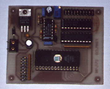
CONSTRUCTION :
The entire circuit is housed on a single small PCB measuring 65mm x 80m. There is no enclosure for the circuit, as that will be left up to the individual application. Mounting holes on the corners of the PCB allow for easy mounting. Before commencing construction, check the PCB for broken tracks and hairline shorts, particularly around the area of RP2 where many tracks pass between pins. Start construction by installing the IC's. A machine pin socket is recommended for the EPROM, as this IC is likely to be changed many times. IC3 should also be mounted in a socket, as this IC is susseptable to damage from outside sources. As usual watch the orientation of the IC's, and observe proper anti- static handling precautions. Next install the two links near IC1, and the resistors and resistor packs. Ensure that the two resistor packs are oriented correctly. There is usually a dot on end of the resistor pack that signifies pin 1. Install the pin headers next. Use the header connector to hold the pins in place when soldering. Complete construction by installing the rest of the components, watching the orientation of the electrolytic capacitors and diode. If the regulator is to be bolted to the PCB, then ensure that it is bolted before soldering the pins to avoid cracking the joints.
TESTING :
Before installing the IC's, apply power to the board and check for +5V on all of the IC pins. Now install the IC's watching for correct polarity. Burn a 27C256 EPROM with the TEST.BIN binary file, and install, once again watching for correct polarity. Note, NEVER remove or install the EPROM with the power applied. Apply power with the jumper pin removed and all inputs LOW, and check that all outputs are all LOW. Next, set each input HIGH in turn and check that the corresponding output goes HIGH. With an oscilloscope or frequency counter, check the frequency ranges of the oscillator. With the jumper connected the range should be from approximately 100Hz to 100KHz, and 0.1Hz to 100Hz with the jumper removed. If all went well, the PLC is now ready for operation.
PROGRAMMING :
In order to use the PLC you must first learn the relatively simple language used by the compiler to generate the binary files used to program the EPROM. You will need a copy of the PLC10.EXE compiler program which is available on the Internet from my home page at http://www.ozemail.com.au/~dljones or alternatively on the Electronics Australia BBS. It is also available from the EA Reader Information Service for those without access to a modem to download the file.
The PLC10.EXE compiler is completely standalone and only requires an ASCII text editor such as the DOS EDIT program to generate the required program text file. The compiler will generate a 32Kbyte un-encoded binary file used for programming the EPROM. This straight binary format is compatible with my software for the 1993 EA EPROM Programer, as well as virtually any other commercial EPROM programmer.
The compiler program is command line driven, and requires the syntax : "PLC10 Inputfile Outputfile" The Inputfile must contain the complete filename and optional path of the text source code. There is no default extension name, although I recommend the extension ".PLC" to differentiate it from other text files. Likewise, the Outputfile must contain the complete filename and optional path of the desired binary file. Once again, there is no default extension name, but ".BIN" is recommended.
The source code syntax is very simple and has the following basic format :
DEFINE Label=00000000
STATE Label
DEFAULT Label
IF 0101xx0 Label
The source code is not case sensitive or "space" sensitive, although there must be a space after the keywords DEFINE, STATE, DEFAULT, and IF.
There must be two basic parts to any source code. The first are the output state definitions which must all be contained at the top of the source code. Each output state definition contains the keyword "DEFINE" followed by the desired name for the state which must not contain spaces. Then an "=" sign followed by the binary output state. The binary output state format must contain eight binary digits either "0" or "1". The first digit represents output 8 followed by outputs 7 to 1. All required output states must be defined before being used further within the source code. The first state zero ("00000000") MUST be defined, as this is the default state after power-on.
The second part contains the definition for each output state. This begins with the keyword STATE followed by the state label already defined. All text after the STATE statement is defined as belonging to that group until the next STATE statement is defined or the end of file is reached. Although the text after the STATE statement does not have to be indented, it helps to improve the clarity of the source code.
For each state there are 128 possible input conditions. By default, all 128 possible input conditions for each STATE will be set to zero. This is to ensure that the hardware will return to state zero in case of a programming or hardware error. The optional DEFAULT command which must be the first command after the STATE command, can be used to change the default condition for the current STATE. The syntax for the DEFAULT command is simply the keyword "DEFAULT" followed by the desired state label. Each of the 128 input conditions for the current state can have it's own IF statement defining the next desired state. The syntax starts with the keyword "IF" followed by the binary input condition and then the desired state label. The binary input condition must be 7 binary digits in length with the first digit representing input seven down to input one. As well as the usual binary states of "0" and "1", the input definition can contain "don't care" conditions which are represented by an "x". For example, "xxx0xx0" would indicate "if input 1 AND input 4 are LOW". Inputs 2,3,5,6, and 7 would be ignored.
Any characters after a "/" will be ignored, and can be used for commenting. Only one command per line is allowed, and blank lines are ignored. The compiler includes extensive error checking and should pick up most syntax errors. If an error is detected, then the compiler will display an error message and the offending line number from the source code. Any error will abort the compiler and return to DOS. The PLC language is easier than it sounds, just follow the example source code and you shouldn't have any problems.
IN USE :
The PLC has an almost limitless number of applications. It can be used to drive relays, LED's, or even digital to analog convertors. If you only require one output to be on at any time, but require more than the eight outputs available, then it would be a simple matter to add decoders to allow up to 256 outputs. This could be useful for a large LED display perhaps. You can similarly expand the inputs up to 128 by adding encoders. The output driver is capable of driving LED's or opto-couplers directly, but a buffer will be required for driving relays or other heavy loads. The frequency adjustment feature allows you to set the speed of the state machine to match the application. 100KHz can be used when the fastest possible respone is required to an input change of state, and 1-10Hz is useful for display applications. When using the low frequency setting, remember that the FSM will require one clock cycle to reset to it's default state when powered on. A clock frequency of 0.1Hz will require at least 10 seconds before the reset condition is achieved. Happy controlling.
|
|
|
| |
Accurate LC Meter
Build your own Accurate LC Meter (Capacitance Inductance Meter) and start making your own coils and inductors. This LC Meter allows to measure incredibly small inductances making it perfect tool for making all types of RF coils and inductors. LC Meter can measure inductances starting from 10nH - 1000nH, 1uH - 1000uH, 1mH - 100mH and capacitances from 0.1pF up to 900nF. The circuit includes an auto ranging as well as reset switch and produces very accurate and stable readings. |
|
PIC Volt Ampere Meter
Volt Ampere Meter measures voltage of 0-70V or 0-500V with 100mV resolution and current consumption 0-10A or more with 10mA resolution. The meter is a perfect addition to any power supply, battery chargers and other electronic projects where voltage and current must be monitored. The meter uses PIC16F876A microcontroller with 16x2 backlighted LCD. |
|
|
|
60MHz Frequency Meter / Counter
Frequency Meter / Counter measures frequency from 10Hz to 60MHz with 10Hz resolution. It is a very useful bench test equipment for testing and finding out the frequency of various devices with unknown frequency such as oscillators, radio receivers, transmitters, function generators, crystals, etc. |
|
1Hz - 2MHz XR2206 Function Generator
1Hz - 2MHz XR2206 Function Generator produces high quality sine, square and triangle waveforms of high-stability and accuracy. The output waveforms can be both amplitude and frequency modulated. Output of 1Hz - 2MHz XR2206 Function Generator can be connected directly to 60MHz Counter for setting precise frequency output. |
|
|
|
BA1404 HI-FI Stereo FM Transmitter
Be "On Air" with your own radio station! BA1404 HI-FI Stereo FM Transmitter broadcasts high quality stereo signal in 88MHz - 108MHz FM band. It can be connected to any type of stereo audio source such as iPod, Computer, Laptop, CD Player, Walkman, Television, Satellite Receiver, Tape Deck or other stereo system to transmit stereo sound with excellent clarity throughout your home, office, yard or camp ground. |
|
USB IO Board
USB IO Board is a tiny spectacular little development board / parallel port replacement featuring PIC18F2455/PIC18F2550 microcontroller. USB IO Board is compatible with Windows / Mac OSX / Linux computers. When attached to Windows IO board will show up as RS232 COM port. You can control 16 individual microcontroller I/O pins by sending simple serial commands. USB IO Board is self-powered by USB port and can provide up to 500mA for electronic projects. USB IO Board is breadboard compatible. |
|
|
|
|
ESR Meter / Capacitance / Inductance / Transistor Tester Kit
ESR Meter kit is an amazing multimeter that measures ESR values, capacitance (100pF - 20,000uF), inductance, resistance (0.1 Ohm - 20 MOhm), tests many different types of transistors such as NPN, PNP, FETs, MOSFETs, Thyristors, SCRs, Triacs and many types of diodes. It also analyzes transistor's characteristics such as voltage and gain. It is an irreplaceable tool for troubleshooting and repairing electronic equipment by determining performance and health of electrolytic capacitors. Unlike other ESR Meters that only measure ESR value this one measures capacitor's ESR value as well as its capacitance all at the same time. |
|
Audiophile Headphone Amplifier Kit
Audiophile headphone amplifier kit includes high quality audio grade components such as Burr Brown OPA2134 opamp, ALPS volume control potentiometer, Ti TLE2426 rail splitter, Ultra-Low ESR 220uF/25V Panasonic FM filtering capacitors, High quality WIMA input and decoupling capacitors and Vishay Dale resistors. 8-DIP machined IC socket allows to swap OPA2134 with many other dual opamp chips such as OPA2132, OPA2227, OPA2228, dual OPA132, OPA627, etc. Headphone amplifier is small enough to fit in Altoids tin box, and thanks to low power consumption may be supplied from a single 9V battery. |
|
|
|
|
|
Arduino Prototype Kit
Arduino Prototype is a spectacular development board fully compatible with Arduino Pro. It's breadboard compatible so it can be plugged into a breadboard for quick prototyping, and it has VCC & GND power pins available on both sides of PCB. It's small, power efficient, yet customizable through onboard 2 x 7 perfboard that can be used for connecting various sensors and connectors. Arduino Prototype uses all standard through-hole components for easy construction, two of which are hidden underneath IC socket. Board features 28-PIN DIP IC socket, user replaceable ATmega328 microcontroller flashed with Arduino bootloader, 16MHz crystal resonator and a reset switch. It has 14 digital input/output pins (0-13) of which 6 can be used as PWM outputs and 6 analog inputs (A0-A5). Arduino sketches are uploaded through any USB-Serial adapter connected to 6-PIN ICSP female header. Board is supplied by 2-5V voltage and may be powered by a battery such as Lithium Ion cell, two AA cells, external power supply or USB power adapter. |
|
200m 4-Channel 433MHz Wireless RF Remote Control
Having the ability to control various appliances inside or outside of your house wirelessly is a huge convenience, and can make your life much easier and fun. RF remote control provides long range of up to 200m / 650ft and can find many uses for controlling different devices, and it works even through the walls. You can control lights, fans, AC system, computer, printer, amplifier, robots, garage door, security systems, motor-driven curtains, motorized window blinds, door locks, sprinklers, motorized projection screens and anything else you can think of. |
|
|
|