| |
2 Channel RF AVR Remote Control |
|
How many times you needed some remote control to handle some electric device ? many times. There are lot of remote controls like infrared, RF, SMS (like my other circuit) and more. The basic small-range remote controls are 2, Infrared and RF (Radio Frequency). One of the weaks of Infrared is that the signal can not pass the walls. So, if you want to control your garage door, the only way is to use some RF remote control. The circuit (transmitter and receiver) use few components and ordinary (I love few component circuits) . Its easy to build it because you don't have to tune-up any coil or variable capacitor. The RF modules are fix to work in 418MHz area.
I have designed this remote control considering :
a.) the check of the received data because many other devices are working in this frequency (418MHz)
b.) and the power-saving of the transmitter. One transmitter must have battery long-life, there is not good to change the battery after 3 days ;) . I don't care about the receiver`s power supply, because receiver must be working all the time.
Features
Transmitter
Standby: <1uA (less than 1 microampere)
only 3v power supply
10...15m distance range
2400bps communication
2 initial bytes for device recognition (ID bytes)
calculate the checksum of the sended data (to avoid fake commands)
few components
small size
Receiver
Hardware UART at 2400bps
4 bytes (32bit) length communication
checksum of the received bytes (to avoid fake commands)
few components
smal size
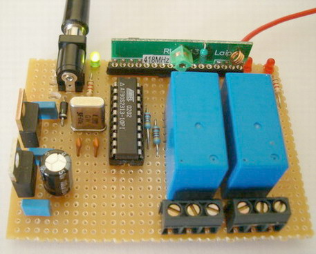
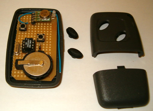
Transmitter description
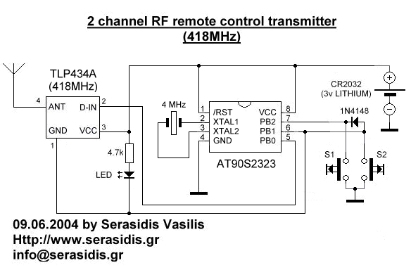
Schematic of the transmitter
The transmitter is constituted by AT90S2323 microcontroller and TLP434 RF transmitter module at 418MHz. I have designe the transmitter for more battery economy and safe transmition of the data.
The battery economy is made it by the use of powerdown mode of AVR. In this case the AVR goes to sleep with less than 1uA (microampere) current and wait for external interrupt on pin PB1 to awake from sleep and continue operating.
If you press the S2 key, the logic of this pin goes to '0' (0V) and AVR awake frome the sleep mode (because PB1 is INT0) and check if pressed the S1 key. If not, the AVR take as pressed key the S2. If yes the AVR take as pressed key the S1.
If you press the S1 key the logic of this pin and PB1 (through 1N4148) goes to '0' (0V). In this case the AVR take as pressed key the S1.
After, calculate the checksum and transmit 4 times the same 4 byte sequence to make sure that receiver takes the data and goes to sleep mode until next interrupt on PB1.
When the INT0 pin (PB1) of AVR goes to 0V, the transmitter TLP434A is working. If you stop press the switch S1 or S2, the TLP is stop working.
The safe transmition of the data based to transmition of 4 bytes with serial form at 2400 bps (bits per seconds). 1st and 2nd byte are for recognition of valid remote control from receiver (like ID bytes), 3rd byte is command byte. The relays status dependet by the value of this byte. Finaly, the 4th byte is the checksum of the earlier 3 bytes.
example: if byte1=30h, byte2=35h and byte3=02h the 4th byte (chechsum) will be (byte1) XOR (byte2) XOR (byte3) = 30h XOR 35h XOR 03h = 06h.
This method use 4 bytes x 8 bit each = 32 bit length (without start and stop bits). That is mean 1 possibility at 4.294.967.295 to receive the receiver, the same 4 bytes from some other RF device.
This transmitter will work with all 2323 chips but better is AT90LS2323 with working voltage 2.7 - 6 volts.The microcontroller that I use is AT90S2323 with working voltage 4 - 6 volts. Its worked fine with 3v lithium battery.
As antenna you can use ~7cm cable in to transmitter`s box.
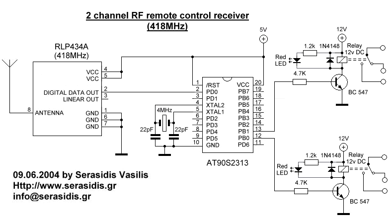
Schematic of the receiver
The receiver constituted by RF receiver module RLP434A at 418MHz, the microcontroller AT90S2313 and the 2 relays with can handle any electric (or electronic) device up to 10 Amps (the contacts of my relays are 10Amp at 250Volts).
The RLP434A is an RF receiver module with receipt frequency at 418MHz with ASK modulation. There are 2 outputs from this module, the digital, with levels from 0v to VCC (5 volts in our case) and the analog output. Analog output is not used. The transmitter send 4 bytes with 2400bps 4 times and the receiver RLP-434A, collect them and move them to AT90S2313 to RxD pin, PD0.
Two reasons to select AT90S2313 (20pins) instead of AT90S2343 (8pins) is because
a.) AT90S2313 use a hardware UART adjusted at 2400bps and the hardware UART is more stable, with smaller code, than software UART that I use in the transmitter. If some serial data arrive at the middle-time of some other routine other than receive routine, for sure we will loose this bits of data. The hardware UART does not have this problem because have buffer for this (UDR register). This is what I mean that the hardware UART is "stable".
b.) with AT90S2313 we can drive up to 14 relays with future upgrade of the firmware, one relay to each pin.
As antenna you can use a cable 30 - 35cm long
The power supply
The power supply of RF receiver constituted by 2 voltage regulator, LM7812 and LM7805. The first (12V) its only to power the 2 relays and the 2nd (5V) to power the AVR microcontroller and the RF receiver module. The LED, is voltage indicator and the 4 capacitors are to flattening the voltage.
Usage of transmitter
Power on the receiver and press S1 key to transmitter. You will see that relay on PB0 of receiver will arm. If you press one more time the same key, the relay will dissarm. If you press S2 key from transmitter you will see that relay on PB1 of receiver will arm. If you press one more time the same key, the relay will dissarm. Each key is for 1 relay only.
I choose to drive 2 relays and not only 1 because for some application like garage door 1 relay can handle the door (open-close) and the other to turn-on or off the light of the garage.
New feature added! roll-code. Roll-code function is increase the safety of remote control, because it is change the transmitting code everytime you press any key on the remote control (AT90S2323 circuit) and the RF thief scanners will be useless!

|
|
|
| |
Accurate LC Meter
Build your own Accurate LC Meter (Capacitance Inductance Meter) and start making your own coils and inductors. This LC Meter allows to measure incredibly small inductances making it perfect tool for making all types of RF coils and inductors. LC Meter can measure inductances starting from 10nH - 1000nH, 1uH - 1000uH, 1mH - 100mH and capacitances from 0.1pF up to 900nF. The circuit includes an auto ranging as well as reset switch and produces very accurate and stable readings. |
|
PIC Volt Ampere Meter
Volt Ampere Meter measures voltage of 0-70V or 0-500V with 100mV resolution and current consumption 0-10A or more with 10mA resolution. The meter is a perfect addition to any power supply, battery chargers and other electronic projects where voltage and current must be monitored. The meter uses PIC16F876A microcontroller with 16x2 backlighted LCD. |
|
|
|
60MHz Frequency Meter / Counter
Frequency Meter / Counter measures frequency from 10Hz to 60MHz with 10Hz resolution. It is a very useful bench test equipment for testing and finding out the frequency of various devices with unknown frequency such as oscillators, radio receivers, transmitters, function generators, crystals, etc. |
|
1Hz - 2MHz XR2206 Function Generator
1Hz - 2MHz XR2206 Function Generator produces high quality sine, square and triangle waveforms of high-stability and accuracy. The output waveforms can be both amplitude and frequency modulated. Output of 1Hz - 2MHz XR2206 Function Generator can be connected directly to 60MHz Counter for setting precise frequency output. |
|
|
|
BA1404 HI-FI Stereo FM Transmitter
Be "On Air" with your own radio station! BA1404 HI-FI Stereo FM Transmitter broadcasts high quality stereo signal in 88MHz - 108MHz FM band. It can be connected to any type of stereo audio source such as iPod, Computer, Laptop, CD Player, Walkman, Television, Satellite Receiver, Tape Deck or other stereo system to transmit stereo sound with excellent clarity throughout your home, office, yard or camp ground. |
|
USB IO Board
USB IO Board is a tiny spectacular little development board / parallel port replacement featuring PIC18F2455/PIC18F2550 microcontroller. USB IO Board is compatible with Windows / Mac OSX / Linux computers. When attached to Windows IO board will show up as RS232 COM port. You can control 16 individual microcontroller I/O pins by sending simple serial commands. USB IO Board is self-powered by USB port and can provide up to 500mA for electronic projects. USB IO Board is breadboard compatible. |
|
|
|
|
ESR Meter / Capacitance / Inductance / Transistor Tester Kit
ESR Meter kit is an amazing multimeter that measures ESR values, capacitance (100pF - 20,000uF), inductance, resistance (0.1 Ohm - 20 MOhm), tests many different types of transistors such as NPN, PNP, FETs, MOSFETs, Thyristors, SCRs, Triacs and many types of diodes. It also analyzes transistor's characteristics such as voltage and gain. It is an irreplaceable tool for troubleshooting and repairing electronic equipment by determining performance and health of electrolytic capacitors. Unlike other ESR Meters that only measure ESR value this one measures capacitor's ESR value as well as its capacitance all at the same time. |
|
Audiophile Headphone Amplifier Kit
Audiophile headphone amplifier kit includes high quality audio grade components such as Burr Brown OPA2134 opamp, ALPS volume control potentiometer, Ti TLE2426 rail splitter, Ultra-Low ESR 220uF/25V Panasonic FM filtering capacitors, High quality WIMA input and decoupling capacitors and Vishay Dale resistors. 8-DIP machined IC socket allows to swap OPA2134 with many other dual opamp chips such as OPA2132, OPA2227, OPA2228, dual OPA132, OPA627, etc. Headphone amplifier is small enough to fit in Altoids tin box, and thanks to low power consumption may be supplied from a single 9V battery. |
|
|
|
|
|
Arduino Prototype Kit
Arduino Prototype is a spectacular development board fully compatible with Arduino Pro. It's breadboard compatible so it can be plugged into a breadboard for quick prototyping, and it has VCC & GND power pins available on both sides of PCB. It's small, power efficient, yet customizable through onboard 2 x 7 perfboard that can be used for connecting various sensors and connectors. Arduino Prototype uses all standard through-hole components for easy construction, two of which are hidden underneath IC socket. Board features 28-PIN DIP IC socket, user replaceable ATmega328 microcontroller flashed with Arduino bootloader, 16MHz crystal resonator and a reset switch. It has 14 digital input/output pins (0-13) of which 6 can be used as PWM outputs and 6 analog inputs (A0-A5). Arduino sketches are uploaded through any USB-Serial adapter connected to 6-PIN ICSP female header. Board is supplied by 2-5V voltage and may be powered by a battery such as Lithium Ion cell, two AA cells, external power supply or USB power adapter. |
|
200m 4-Channel 433MHz Wireless RF Remote Control
Having the ability to control various appliances inside or outside of your house wirelessly is a huge convenience, and can make your life much easier and fun. RF remote control provides long range of up to 200m / 650ft and can find many uses for controlling different devices, and it works even through the walls. You can control lights, fans, AC system, computer, printer, amplifier, robots, garage door, security systems, motor-driven curtains, motorized window blinds, door locks, sprinklers, motorized projection screens and anything else you can think of. |
|
|
|