| |
Intelligent NiCd/NiMH Battery Charger |
|
This cheap and easy to build NiCd/NiMH Battery Charger is suitable for automatically charging a wide range of batteries for many applications. Proper chargers are usually expensive and cheap chargers supplied with the original equipment often incorrectly charge the cells and dramatically shorten their life. This 'intelligent' charger was designed for high current and rapid charge applications such as cordless power tools and model racing cars. These battery packs are expensive and sometimes difficult to purchase. This charger uses the cell manufacturer's recommended charge method, to safely and quickly charge batteries.
Introduction
As a handyman myself I have a certain amount of power tools. The power source of cordless tools ranges from 3.6V to 18V and almost inevitably consists of Sanyo or Panasonic NiCd/NiMH cells, despite the actual brand of the power tool itself. Properly treated, these battery packs should be good for hundreds of charges and could potentially last many years.
Recently I found my 2-year-old 9.6V cordless drill battery wouldn't perform to its rated capacity after charging. Unfortunately the battery packs are fairly expensive to replace, sometimes costing almost as much as the entire drill kit, if in fact you can purchase the batteries separately at all. Often you will get told to just "buy a new drill". It is cheaper to purchase your own cells and use the old case to manufacture a battery pack, if you can do the soldering of the battery tags (Note: don't solder directly to the batteries as is damages them and is quite dangerous).
In selecting replacement cells, I researched the manufacturer's specifications on charging and guess what? The battery charger that came with the drill didn't comply with these specifications. In other words, the supplied battery charger is a very simple device that applies constant current to the battery pack. There is no charge termination method used by the charger. During the recharging process, once batteries reach their 100% charge, the cell starts to heat and the internal pressure builds up, causing the battery to eventually rupture or vent electrolyte.
Having paid good money for a new battery pack, I decided to design a new charger that would not damage the battery. I decided from the specifications and from my preferred style of use (throw it in the charger and expect it to be good next time I reached for it) that the design of a better battery charger would require the charger to sense the condition of cells and charge accordingly.
To perform this task requires a device that measures, remembers and controls which state the charge should be in, and when coupled with some complex characteristics that rechargeable batteries can exhibit, it seemed to me that logic control circuitry was required. I wanted to keep the design as simple as possible, and reduce the component count, because reducing the size and number of holes in the PCB is the major cost driver in circuit manufacture. I soon realised that the simplest design would be a one-chip design, and that was to use a PIC. (PIC stands for the PIC16C711 Peripheral Interface Controller and is a registered trademark of MicroChip). If you don't have a PIC programmer, don't panic! This component is available inexpensively from the author of this project. Other than this, very simple and commonly available components enable this project to be completed for about $50, which is a lot cheaper than your next battery pack!
NiCd/NiMH Cell Characteristics
Even if you don't want to build this charger, you can still stand to gain something from this article by understanding how to get the most from your rechargeable batteries. To start with a cell is defined as a single vessel containing electrodes and electrolyte for generating current. A battery consists of two or more cells. NiCd/NiMH cells are rated at 1.2V for design purposes although they normally develop about 1.25V. Under full charge they require about 1.5V to 1.6V. They can supply very large amounts of current and display a remarkably flat discharge characteristic, maintaining a consistent 1.2V throughout discharge. The voltage then drops quite suddenly, and they are almost completely flat at 0.8V. This is called the "knee" characteristic because of the shape of the graph of voltage against time.
Rechargeable battery capacity is rated in mAH (milliampere-hours). The total capacity of a battery is defined as "C", that is it can supply C mA for 1 hour, or 2C for 30 minutes etc. Charge rates can vary from trickle charges to keep the battery 'topped up' of 3.3% of C to 5% of C, a slow current charge of 10% of C to 20% of C or a fast charge of 50% of C to 100% of C. Slow charges are not meant to be continually applied, and since NiCd/NiMH batteries are about 66% efficient, they normally last about 8-15 hours. Fast charges such as 100% of C should be terminated after about 1.5 hours, providing the battery is flat to begin with. Once a battery is fully charged, the battery produces gas creating a high internal pressure, and a sudden rise in temperature. The charge should be switched to a trickle charge at this point or the battery will begin to vent and release its electrolyte. My old battery was rated at C=1300mAH and my old charger was rated 400mA (30% of C) so the charger should have been switched off after about 4 hours, provided that they were almost flat to begin with. However there is no way of knowing if C was actually 1300maH or if it had decreased a bit, and once the a battery starts to deteriorate, I suspect this becomes a vicious cycle and the battery deteriorates rapidly due to more and more overcharging. The manufacturer suggests these cells should be good for 500 to 1000 cycles if properly treated!
The Memory Effect Myth
Possibly the biggest myth that exists partcularly for NiCd cells is the "memory effect". Almost every one quotes it as the reason that cells have to be completely flattened - otherwise they develop some sort of memory, and can only hold a partial charge from there on. Like all good stories, this one has a grain of truth in it! The myth originated from the early days of satellites when they were using solar cells to charge batteries and because of the orbiting of the craft around the earth, the batteries were subjected to precise charge/discharge cycles many hundreds of times. The effect disappears when the battery cycle is suddenly varied, and it is extremely difficult to reproduce this effect even in a laboratory. So the "memory effect" is not a significant problem in home usage.
What I can tell you is while it may be OK to discharge individual cells to 0V, it is certainly not recommended to discharge an entire battery of cells. The reason is simple. When the battery is discharged below 0.8V per cell, one of the cells is inevitably weaker than the others, and goes to zero first. If the battery is further flattened this battery becomes charged in reverse, which again makes it still weaker. This creates a more common but less commonly known effect called "voltage depression". Eventually the battery's performance drops off quite suddenly which ironically is the very thing that the user is trying to prevent. Most users know where the battery's "knee" occurs; it is when the original equipment first starts to show signs that the battery performance (and hence voltage) is suddenly dropping, and it is a good idea to place it straight on charge at this point. Usually there is less than 5% of C remaining anyway.
One other thing, batteries don't like getting too hot or cold; they do not take a full charge and they actually discharge (even under no load) much faster when over 40 degrees or below 0 degrees. They can build up internal heat when working and this can cause temperatures inside to increase also. Particularly avoid leaving cordless tools inside a hot car for this reason. They also should be left to cool down for a while after discharge before placing them on charge. NiCd/NiMH batteries do self-discharge too, as a rule of thumb a battery will hold a full charge (with no load) for about a month or two, although when they get old or hot, they might only last a day.
So what can you learn from this?
* You don't have to flatten your battery before you recharge it,
* Don't flatten your battery below 0.8V per cell,
* Don't overcharge your battery beyond 100% of C, and
* NiCd/NiMH don't like to get too hot, or too cold (0 to 40 degrees C is usually best)
NiCd/NiMH Charging
Common values for C for cordless tools and racing cars are in the range from 1000maH to 3000maH. The first step is to determine what C is for your cells. Inspect the cells or contact the manufacturer to determine the cell part number. In drills, the battery packs can often be disassembled easily. The value for C often forms some of the part number and the part number can be searched for on the Internet. For my new battery the value for C was 1700maH. Note that the cell value for C is the same as the battery value for C.
Manufacturers data gives that when designing a charger you should first consider how the cells are to be used. For these applications the charge use is termed "cycle use" where the battery is repeatedly charged and discharged. In addition, usually the charge time required is as fast as possible, between 1 and 2 hours. My batteries were capable of taking a fast charge of 100% of C, which equates to 1.7A. Despite this I conservatively selected 1.25A as my charge current, because I wished to be able to charge 1300maH batteries also. This value should be good for most readers, and it doesn't really matter if it is a bit less than 100% of C, because the charger will still detect a peak eventually anyway. However, some readers will want to adjust the maximum current, and this is described a bit later on.
For "cycle use", there are two recommended methods of detecting charge termination, either using a temperature sensor in the battery pack or using a "negative delta V" cutoff system. The temperature technique relies on detecting the sudden rise in battery temperature to shut off the charge. There is nothing wrong with doing this but battery packs do not always come with temperature sensors built in. Furthermore ones that do, often sense the temperature of only one cell.
The negative delta V system relies on the electrical characteristic that the NiCd/NiMH battery voltage peaks and drops about 20mV per cell when fully charged. This charger in its basic configuration will detect a peak of 84mV (per battery) from 2V to 21.5V, and thus will charge any battery pack in this range (i.e. 6-12 cells or 7.2V to 14.4V). Options to alter this range are described in Figure 10. Hence, no matter how discharged the battery is, this technique will give enough charge to restore the battery to its full state, and then the battery is continually "topped up" with a trickle charge to prevent slow leakage through internal resistance.
Other things to consider are the requirement to let a battery cool down, so a better charge can be applied. This battery charger waits for the battery voltage to stabilize for about 30 seconds before starting to charge. If the battery has just come off discharge and is hot, it may take a minute or so for the charge to begin to start. Additionally new batteries may show false peaks in the first 4 minutes of charge. For this reason the charger starts with a slow "soft start" charge for 4 minutes to allow the battery to cool and get past this point.
The charger uses a threshold of 2V (open circuit voltage) to recognize that a battery has been connected. In practice even a very old battery that has been actually shorted out for some time, will recover above this value when unloaded. The charging algorithm used by the PIC is shown in Fig 1. Note that the first Light Emitting Diode (LED) comes on continually whilst battery is undergoing the bulk charge process, while the second LED gives an indication of the particular type of charge being applied.
Normal operation of the charger is fairly straightforward. Normally the Charger is switched on and both LEDs will flash once. The charger will then wait in mode 0 (standby) until a battery is connected. Once a battery is connected, the charger will progress though mode 1 (cool), 2 (soft), 3 (fast) and 4 (trickle). The battery can be left in mode 4 (trickle) indefinitely, or removed at this point. When the battery is removed, the charger will revert to mode 0 (standby).
Operating Principle
The circuit was first designed as a block diagram shown in Fig 2. A constant current supply is switched on and off as required by a micro-controller. The micro-controller senses the battery voltage and internally uses an analog to digital converter to read the battery voltage. The micro-controller, requires its own 5V regulated supply and displays the current charging status on two LEDs. The smallest and cheapest micro-controller that could be used to perform the Analog to Digital function and still have the necessary functions and control lines to do this is the PIC16C711. It is an 8 bit, high performance CMOS 4MHz CPU, that has 4 Analog to Digital converters, a brown out timer and a watchdog timer which are used in this circuit to reset the chip if problems occur such as power transients or dips. It comes in an 18-pin dual in line package. It has on board a massive 1K words of program memory and 68 bytes of data. Hardly enough to load Windows 2000 on I know, but quite enough to write a control program on - makes you wonder doesn't it!
The final circuit is shown in Fig 3. The circuit consists of a bridge rectifier and capacitor to reduce the ripple under a full 1.5A load to about 1V. A 5V rail for the PIC is developed through a 7805 3-pin regulator. The crystal and 27pF capacitors provide a stable and accurate 4 MHz time base for the PIC. This is necessary to ensure accurate time delay functions for charging. The monolithic 0.1uF capacitor provides decoupling. The two LEDs are driven directly from the PIC via current limiting 100ohm resistors. The 3.3Kohm and 1Kohm resistor "divide" the battery voltage from about 0-21.5V to 0-5V which is the range of the PIC's Analog to Digital converter.
The LM317 will maintain 1.25V between the OUT pin and the ADJ pin. I used a large 1ohm, 5W resistor here to ensure a constant 1.25A supplied. You can select this value as suits your application. Just use Ohms law and divide the 1.25Volts by the current that is recommended for full charge. For example 0.68 ohms will provide about 1.7A and 1.2 ohms will provide about 1A. The IN5404 diode ensures that the circuit charges the battery, and prevents the battery running the circuit, should the input power be accidentally turned off! If this does occur with a fully charged pack, the diode isolates the circuit and upon turn on the charger will find the battery peak again and return to a trickle charge after just a few minutes.
When the transistor is biased on, it effectively takes the ADJ pin to about 0.2V. This means the output voltage of the whole unit is about 0.5V. The transistor is biased on by default, to ensure that the unit is "fail-safe". The PIC can turn the transistor off by shorting the base to ground, and this allows the LM317 to provide a regulated, constant current output. The drive current for the PIC, the transistor base and the transistor collector are all in the order of 1mA which is within the rated range of the PIC and transistor.
A final feature of the software is that there is a Built-In-Test (BIT) upon power up that effectively tests all of the components except the capacitors (more than 80% of the components). During power up, if no battery is detected (i.e. less than 2V on the output), the output is turned on for 1 second and the voltage checked, and then the output is turned off. If the voltage does not reach at least 10V when high and go below 2 V when low, then an error is detected. The LEDs are both powered on simultaneously during this BIT. If there is an error the LEDs then flash alternately like a train crossing. This mode can be verified by shorting the output on power up or plugging in a battery during the BIT. The error mode will also be invoked if no peak is detected after 3 hours of main charge.
Construction
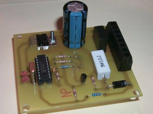
The circuit was developed and tested in full on breadboard and finally made on a Printed Circuit Board (PCB). The PCB bottom layer and top overlay are shown in Fig 4 and Fig 5. The board is copyright to the designer, but home users can make their own board for personal use. The board cannot be manufactured for commercial use. The board was designed to be single sided with thick tracks and gentle curves, so it could be easily manufactured even at home, there are no vias or jumpers and all components can be directly soldered on the board. The LEDs can be directly mounted on the board on the solder side and can then pass through the centre of the front panel if required, or they can be connected via wires and mounted separately. The circuit also delivers a large current, so the high current tracks on the board have been deliberately made short and thick to carry the load.
Charger Assembly
A complete parts list is included in Fig 6. The circuit is easy to construct in a few hours, however the constructor will need to be careful with the polarity with some components, namely the transistor, the electrolytic capacitor, the IC and the diode. If in doubt about the polarity of any components check the circuit, the overlay and/or refer to a data book for the pin outs. The No 1 pin of the PIC is next to the divot in the chip and faces the side of the board furthest away from the LEDs.
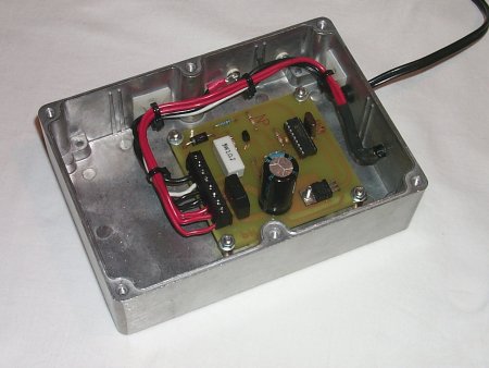
Charger Heat Sink
For the connections to the LM317, you can download the datasheet in pdf form from the bottom of this page. The LM317 must be mounted to a heat sink of 5 degrees per watt or less. In my final design the LM317 was mounted to the case of a die cast aluminum box. The box needs to be the specified size for heat dissipation. It will need to be bolted to the case tightly with silicon grease applied underneath to ensure a good thermal contact. The LM317 needs to be electrically isolated from the case by a silicon washer and grommet kit for a TO3 style transistor. The use of heat sink compound is recommended. The LM317 will drop about 10V at 1.25A i.e. 12 Watts when charging smaller batteries and can get warm. If higher power dissipation is required, the LM317 will need to be mounted on a heat sink. Don't forget to clean all of the flux off the board with a toothbrush soaked in methylated spirits, as over time flux will corrode your solder joints and tracks. A quick spray of clear varnish is recommended to prevent any corrosion; but ensure you mask the IC socket, the LEDs and the terminals first.
Testing/Operation
The bridge rectifier and capacitor should produce about 1.4 times the AC RMS input. So if using a 16VAC supply, the main rail should be about 22VDC. If using 24VAC, this rail will be about 30VDC. At least 2.5V is dropped through the LM317, current sensing resistor and output diode. Also check that the 5V rail is regulating properly.
The unit requires 24VAC input to charge 14.4V batteries, although only 16VAC is required to charge anything smaller. The AC power source must be rated at the chosen supply current or better. If you are a beginner I recommend the use of an external "plug pack", however you could mount a mains transformer inside the unit, if you are competent to carry out mains wiring but you will obviously need a larger box.
Charger In Use
For the connection to the battery, I used my existing charger pack. I removed the internal circuitry, which was no more than a transistor and LED that indicated that current was being delivered. For power connections, EIAJ DC Voltage connectors and plugs are standard, with the positive usually being the centre pin. It is wise to select your pin sizes so that the AC cannot be plugged from the AC plug pack to the charger, if you use this setup.
To explain the various control modes to the user, the artwork for the front panel includes a legend for understanding the flashing LED indications. This artwork is included as Fig 7.
The circuit was tested using a voltage data logger and the results of this are included as Fig 8 and Fig 9 which show the original and new charge profiles respectively. Note particularly the new charge profile switching to trickle charge when a peak is established.
Conclusion
The charger was easy to construct, and has been demonstrated to charge effectively and safely many times. As a result of this project my charging time has halved from 3-4 hours to 1.5 hours maximum. I now merely pull the battery from my drill and throw it in the charger, knowing that I can just grab it and use it whenever I next go to the shed, which is the way it should be.
The circuit described will charge any NiCd/NiMH battery in the range 7.2V to 14.4V as is; however many constructors have Emailed me requesting details of how to alter the charging range to charge other battery packs. You will need to verify that the battery is still peak detecting properly, but some suggested values are at Fig 10.
Interested constructors may mail order their pre-programmed and tested PIC chips directly from the designer of this project for $AUD20 plus $AUD5 post and packaging. The source code is not freeware or shareware so please don't ask me to mail you the source code as it has commercial applications. Free support is available if you have any problems with the construction of this project, and many hundreds have been sold in Australia and overseas. Click on the button below to order a PIC.
RCS RadioThe blank printed circuit board is coded 14104011 and is available from RCS Radio Australia phone 61 2 9738 0330. Click on the logo to go to the RCS website.

Related Links
Downloads
Intelligent NiCd/NiMH Battery Charger - Link
|
|
|
| |
Accurate LC Meter
Build your own Accurate LC Meter (Capacitance Inductance Meter) and start making your own coils and inductors. This LC Meter allows to measure incredibly small inductances making it perfect tool for making all types of RF coils and inductors. LC Meter can measure inductances starting from 10nH - 1000nH, 1uH - 1000uH, 1mH - 100mH and capacitances from 0.1pF up to 900nF. The circuit includes an auto ranging as well as reset switch and produces very accurate and stable readings. |
|
PIC Volt Ampere Meter
Volt Ampere Meter measures voltage of 0-70V or 0-500V with 100mV resolution and current consumption 0-10A or more with 10mA resolution. The meter is a perfect addition to any power supply, battery chargers and other electronic projects where voltage and current must be monitored. The meter uses PIC16F876A microcontroller with 16x2 backlighted LCD. |
|
|
|
60MHz Frequency Meter / Counter
Frequency Meter / Counter measures frequency from 10Hz to 60MHz with 10Hz resolution. It is a very useful bench test equipment for testing and finding out the frequency of various devices with unknown frequency such as oscillators, radio receivers, transmitters, function generators, crystals, etc. |
|
1Hz - 2MHz XR2206 Function Generator
1Hz - 2MHz XR2206 Function Generator produces high quality sine, square and triangle waveforms of high-stability and accuracy. The output waveforms can be both amplitude and frequency modulated. Output of 1Hz - 2MHz XR2206 Function Generator can be connected directly to 60MHz Counter for setting precise frequency output. |
|
|
|
BA1404 HI-FI Stereo FM Transmitter
Be "On Air" with your own radio station! BA1404 HI-FI Stereo FM Transmitter broadcasts high quality stereo signal in 88MHz - 108MHz FM band. It can be connected to any type of stereo audio source such as iPod, Computer, Laptop, CD Player, Walkman, Television, Satellite Receiver, Tape Deck or other stereo system to transmit stereo sound with excellent clarity throughout your home, office, yard or camp ground. |
|
USB IO Board
USB IO Board is a tiny spectacular little development board / parallel port replacement featuring PIC18F2455/PIC18F2550 microcontroller. USB IO Board is compatible with Windows / Mac OSX / Linux computers. When attached to Windows IO board will show up as RS232 COM port. You can control 16 individual microcontroller I/O pins by sending simple serial commands. USB IO Board is self-powered by USB port and can provide up to 500mA for electronic projects. USB IO Board is breadboard compatible. |
|
|
|
|
ESR Meter / Capacitance / Inductance / Transistor Tester Kit
ESR Meter kit is an amazing multimeter that measures ESR values, capacitance (100pF - 20,000uF), inductance, resistance (0.1 Ohm - 20 MOhm), tests many different types of transistors such as NPN, PNP, FETs, MOSFETs, Thyristors, SCRs, Triacs and many types of diodes. It also analyzes transistor's characteristics such as voltage and gain. It is an irreplaceable tool for troubleshooting and repairing electronic equipment by determining performance and health of electrolytic capacitors. Unlike other ESR Meters that only measure ESR value this one measures capacitor's ESR value as well as its capacitance all at the same time. |
|
Audiophile Headphone Amplifier Kit
Audiophile headphone amplifier kit includes high quality audio grade components such as Burr Brown OPA2134 opamp, ALPS volume control potentiometer, Ti TLE2426 rail splitter, Ultra-Low ESR 220uF/25V Panasonic FM filtering capacitors, High quality WIMA input and decoupling capacitors and Vishay Dale resistors. 8-DIP machined IC socket allows to swap OPA2134 with many other dual opamp chips such as OPA2132, OPA2227, OPA2228, dual OPA132, OPA627, etc. Headphone amplifier is small enough to fit in Altoids tin box, and thanks to low power consumption may be supplied from a single 9V battery. |
|
|
|
|
|
Arduino Prototype Kit
Arduino Prototype is a spectacular development board fully compatible with Arduino Pro. It's breadboard compatible so it can be plugged into a breadboard for quick prototyping, and it has VCC & GND power pins available on both sides of PCB. It's small, power efficient, yet customizable through onboard 2 x 7 perfboard that can be used for connecting various sensors and connectors. Arduino Prototype uses all standard through-hole components for easy construction, two of which are hidden underneath IC socket. Board features 28-PIN DIP IC socket, user replaceable ATmega328 microcontroller flashed with Arduino bootloader, 16MHz crystal resonator and a reset switch. It has 14 digital input/output pins (0-13) of which 6 can be used as PWM outputs and 6 analog inputs (A0-A5). Arduino sketches are uploaded through any USB-Serial adapter connected to 6-PIN ICSP female header. Board is supplied by 2-5V voltage and may be powered by a battery such as Lithium Ion cell, two AA cells, external power supply or USB power adapter. |
|
200m 4-Channel 433MHz Wireless RF Remote Control
Having the ability to control various appliances inside or outside of your house wirelessly is a huge convenience, and can make your life much easier and fun. RF remote control provides long range of up to 200m / 650ft and can find many uses for controlling different devices, and it works even through the walls. You can control lights, fans, AC system, computer, printer, amplifier, robots, garage door, security systems, motor-driven curtains, motorized window blinds, door locks, sprinklers, motorized projection screens and anything else you can think of. |
|
|
|