| |
PICkit2 Compatibile MPLAB Programmer |
|
This is a PICkit 2 MPLAB compatibile Programmer. It is a low-cost development tool with an easy to use interface for programming and debugging Microchip’s Flash families of microcontrollers. The full featured Windows programming interface supports baseline (PIC10F, PIC12F5xx, PIC16F5xx), midrange (PIC12F6xx, PIC16F), PIC18F, PIC24, dsPIC30, dsPIC33, and PIC32 families of 8-bit, 16-bit, and 32-bit microcontrollers, and many Microchip Serial EEPROM products. With Microchip’s powerful MPLAB Integrated Development Environment (IDE) the PICkit 2 enables in-circuit debugging on most PIC microcontrollers. In-Circuit-Debugging runs, halts and single steps the program while the PIC microcontroller is embedded in the application. When halted at a breakpoint, the file registers can be examined and modified.

PICkit2 is a very powerful device, in addition to a PIC-programmer function it can be used as a serial EEPROM programmer or a debugger with certain PICs. Since PICkit2 is a Microchip product they are continuously updating the software and the firmware to support the newer and newer PICs. You can program virtually the entire range of 8 bit MCUs, the 16 bit 24H and dsp series and even the newest 32 bit famliy with PICkit2.
In addition of the above PICkit2 uses USB interface to communicate with the computer, so there's no more pain to use it with modern PCs or laptops with no COM or LPT ports at all. Because Microchip has published the whole schematics and the firmware running in the device we have the chance to rebuild it.
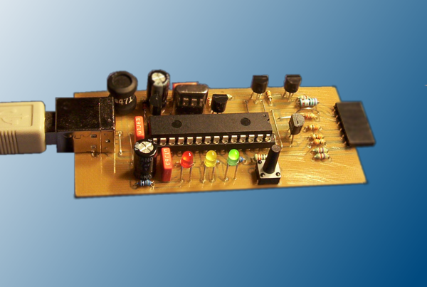
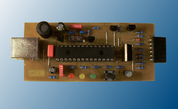
The PICkit2 clone has been designed using only hole-mounted parts as it has less problems to rebuilding. I've also simplified the schematic, so the clone can be built to the same size PCB as the original PICkit2:
* The main difference is that the clone supports 5V power supply only, thats why 3.3V devices will require a small additional board which will be published soon.
* The second change is that I have omitted the two 24C512 EEPROMs that were in the original PICkit2. These are only used for programmer-to-go function, but I think it is absolutely not important capability for a hobbyist.
* The third modification is that MOSFETs are working in the clone instead of bipolar transistors, so minimal additional components are needed. You may find that the Q3 FET switching the power supply towards the target circuit is unnecessarily overrated, however, this allows us to achieve the lowest possible voltage-drop on the power line.
* Finally I've used USB-B connector on the clone. A cable with this type of connector is almost at everybody's hand, or can be bought for some cents. The original miniUSB connector is more expensive and may cause more difficulties to buy.
You can see the schematics on the picture above. All the operations are accomplished by the PIC18F2550. This communicates with the host computer via USB bus, controls the Vpp pump if necessary, switches Vdd and drives the lines to the target circuit. The built-in clock generator uses X1 with C2 and C3 to ensure the correct system clock rate.
L1, Q1, D1, C1 and C4 form a boost DC-DC converter which is controlled by the PIC firmware. The voltage sensing feedback is built from R2 and R3, so the control loop is complete. Q4 and Q5 with R5 are for switching Vpp to the MCLR/Vpp output. Q6 with R4 gives an active pull-down to MCLR line when it is needed. LED1 (green, with R12) shows that the clone consumes power supply from the USB.
R16 and Q3 are for switching the Vdd on the output Vdd line. Vdd sensing feedback to the PIC is worked up with R6. Q2 with R1 and R17 form the active pull-down at the output Vdd line. The D2 (if fitted) only protects the circuit against external voltage from Vdd. Yellow colored LED2 (with its series resistor R11) indicates that Vdd is switched to the output.
The red LED3 (with R10) is controlled by the firmware to indicate different states of operating. Normally it lights during the read and write operations, means "busy" state.
R7, R8 and R9 are current limiting resistors in series the output lines PGD, PGC and AUX. R15 and R14 ensures the low level at the PGD and PGC lines in certain cases.
C5, C6 and C7 are power-line decoupling capacitors while R13 acts as a discharger load after disconnecting the device from USB.
S1 push-button has two functions:
* holding down during connecting PICkit2 to the USB the device starts in a special bootloader mode - in this mode only downloading a new firmware is available from the PICkit2 handling software;
* during normal operation a push can trigger the handling software to reload the last used hex file and program it to the attached device if this is enabled in the software.
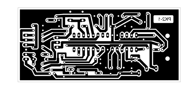
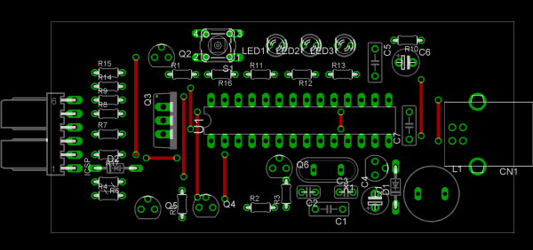
The PCB design and fitting picture are shown below. It is one-sided, only some straight wires can be found on the component side (red lines). This makes it easy to print the board at home too. I put a text onto the PCB to make easier to identify the right side of the layout. This is a crucial part that you have to be able to read the text on the copper - so you can double check it before the etching. Layout has been exported from Eagle into PNG format with 600 dpi resolution. A friend of mine had been converted the image to PDF, it looks fine too. The pictures with the original size and Eagle files can be found in the package at the bottom of this page.
You must know that protection diode D2 (BAT85 on schematics) drops much more voltage on Vdd line than the switching FET Q3. If you wish, the voltage drop of the protection diode can be eliminated by shorting the place of it. If you don't want to totally cancelling this protection, you can use a lower drop type, eg. 1N5819.
The PIC is better to build in using a socket. Design around Q3 allows you to replace the Q3 (IRF9Z34) with a significantly cheaper BC640 bipolar transistor (as you can see on my prototype). In this case the output current is limited to a few hundred milliamperes with an acceptable voltage drop.
Otherwise, assembling the board is not a complicated task, although bewaring of the accidental shorts is essential. After populating the PCB up you would check the electrical connections with a buzzer (continuity tester).
Unfortunately to start the clone you have to program the firmware into the 18F2550 - you will need a secondary programmer for this. Once the PICKit2 firmware has been programmed into the 18F2550, you can upgrade it without the need of another programmer, because the firmware also includes a bootloader.
The newest firmware version always can be found at Microchip's site, but the current version is also in the package of this article at our download area - click here to download!
After electrical checks against unwanted short- or open circuits on the PCB wires the board can be attached to a computer. Connecting the clone to the USB, the PC should detect it as a HID compliant device. In a Windows XP system open the device manager and check if it is there. Next, start the handling software "PICkit2" and check the status reported by it. The status should show "PICkit2 connected." text and shouldn't be red backgrounded.
If it seems to be all right, you should click on "troubleshoot" from "tools" menu and follow through the troubleshooting wizard. This procedure requires a voltage meter. Note, that the clone cannot regulate voltage on output Vdd line, so changing it in the PICkit2 program is irrelevant. You should always measure approximately the USB voltage (5V) on the Vdd output when it is turned on.
When you walked through the wizard without any errors you are able to start using your brand new PICkit2 clone, congratulations!
Related Links
Downloads
 HEX Program
PICkit2 Compatibile MPLAB Programmer
HEX Program
PICkit2 Compatibile MPLAB Programmer - Link
|
|
|
| |
Accurate LC Meter
Build your own Accurate LC Meter (Capacitance Inductance Meter) and start making your own coils and inductors. This LC Meter allows to measure incredibly small inductances making it perfect tool for making all types of RF coils and inductors. LC Meter can measure inductances starting from 10nH - 1000nH, 1uH - 1000uH, 1mH - 100mH and capacitances from 0.1pF up to 900nF. The circuit includes an auto ranging as well as reset switch and produces very accurate and stable readings. |
|
PIC Volt Ampere Meter
Volt Ampere Meter measures voltage of 0-70V or 0-500V with 100mV resolution and current consumption 0-10A or more with 10mA resolution. The meter is a perfect addition to any power supply, battery chargers and other electronic projects where voltage and current must be monitored. The meter uses PIC16F876A microcontroller with 16x2 backlighted LCD. |
|
|
|
60MHz Frequency Meter / Counter
Frequency Meter / Counter measures frequency from 10Hz to 60MHz with 10Hz resolution. It is a very useful bench test equipment for testing and finding out the frequency of various devices with unknown frequency such as oscillators, radio receivers, transmitters, function generators, crystals, etc. |
|
1Hz - 2MHz XR2206 Function Generator
1Hz - 2MHz XR2206 Function Generator produces high quality sine, square and triangle waveforms of high-stability and accuracy. The output waveforms can be both amplitude and frequency modulated. Output of 1Hz - 2MHz XR2206 Function Generator can be connected directly to 60MHz Counter for setting precise frequency output. |
|
|
|
BA1404 HI-FI Stereo FM Transmitter
Be "On Air" with your own radio station! BA1404 HI-FI Stereo FM Transmitter broadcasts high quality stereo signal in 88MHz - 108MHz FM band. It can be connected to any type of stereo audio source such as iPod, Computer, Laptop, CD Player, Walkman, Television, Satellite Receiver, Tape Deck or other stereo system to transmit stereo sound with excellent clarity throughout your home, office, yard or camp ground. |
|
USB IO Board
USB IO Board is a tiny spectacular little development board / parallel port replacement featuring PIC18F2455/PIC18F2550 microcontroller. USB IO Board is compatible with Windows / Mac OSX / Linux computers. When attached to Windows IO board will show up as RS232 COM port. You can control 16 individual microcontroller I/O pins by sending simple serial commands. USB IO Board is self-powered by USB port and can provide up to 500mA for electronic projects. USB IO Board is breadboard compatible. |
|
|
|
|
ESR Meter / Capacitance / Inductance / Transistor Tester Kit
ESR Meter kit is an amazing multimeter that measures ESR values, capacitance (100pF - 20,000uF), inductance, resistance (0.1 Ohm - 20 MOhm), tests many different types of transistors such as NPN, PNP, FETs, MOSFETs, Thyristors, SCRs, Triacs and many types of diodes. It also analyzes transistor's characteristics such as voltage and gain. It is an irreplaceable tool for troubleshooting and repairing electronic equipment by determining performance and health of electrolytic capacitors. Unlike other ESR Meters that only measure ESR value this one measures capacitor's ESR value as well as its capacitance all at the same time. |
|
Audiophile Headphone Amplifier Kit
Audiophile headphone amplifier kit includes high quality audio grade components such as Burr Brown OPA2134 opamp, ALPS volume control potentiometer, Ti TLE2426 rail splitter, Ultra-Low ESR 220uF/25V Panasonic FM filtering capacitors, High quality WIMA input and decoupling capacitors and Vishay Dale resistors. 8-DIP machined IC socket allows to swap OPA2134 with many other dual opamp chips such as OPA2132, OPA2227, OPA2228, dual OPA132, OPA627, etc. Headphone amplifier is small enough to fit in Altoids tin box, and thanks to low power consumption may be supplied from a single 9V battery. |
|
|
|
|
|
Arduino Prototype Kit
Arduino Prototype is a spectacular development board fully compatible with Arduino Pro. It's breadboard compatible so it can be plugged into a breadboard for quick prototyping, and it has VCC & GND power pins available on both sides of PCB. It's small, power efficient, yet customizable through onboard 2 x 7 perfboard that can be used for connecting various sensors and connectors. Arduino Prototype uses all standard through-hole components for easy construction, two of which are hidden underneath IC socket. Board features 28-PIN DIP IC socket, user replaceable ATmega328 microcontroller flashed with Arduino bootloader, 16MHz crystal resonator and a reset switch. It has 14 digital input/output pins (0-13) of which 6 can be used as PWM outputs and 6 analog inputs (A0-A5). Arduino sketches are uploaded through any USB-Serial adapter connected to 6-PIN ICSP female header. Board is supplied by 2-5V voltage and may be powered by a battery such as Lithium Ion cell, two AA cells, external power supply or USB power adapter. |
|
200m 4-Channel 433MHz Wireless RF Remote Control
Having the ability to control various appliances inside or outside of your house wirelessly is a huge convenience, and can make your life much easier and fun. RF remote control provides long range of up to 200m / 650ft and can find many uses for controlling different devices, and it works even through the walls. You can control lights, fans, AC system, computer, printer, amplifier, robots, garage door, security systems, motor-driven curtains, motorized window blinds, door locks, sprinklers, motorized projection screens and anything else you can think of. |
|
|
|