| |
Infra Red Vision System for a Toy Cars |
|
This is the project of infrared vision system for a toy car. It will project 2 modulated IR beams ahead and detect any reflection of these beams on any obstacle ahead of the car. The circuit will then invert the car's motor for a given time thus changing the direction of advance as it goes in reverse. No special control for steering is necessary as the car has the front wheels' shaft in an eccentric support: when going forward it auto aligns itself, when running backwards the shaft turns and the car describes a curve.

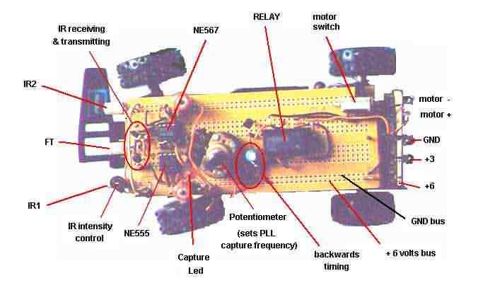
The main circuit given above is mounted on a PC board that will be fixed over the car. Ahead and on the sides we'll put the IR emitting diodes (2), in the center, the IR reception photo transistor FT. Also the capture frequency potentiometer for easy adjust is located above, on the PC board.
Principal details
The original toy had a wireless remote control unit transmitter with only 1 channel, backwards. The car normally runs forward but upon signal reception the car's circuit inverts the motor polarity and the car runs backwards. As shown in Fig 1, the front wheel shaft is fixed at an eccentric point S in relation with car's centerline. When the car is reversing, the front shaft also turns due to the different friction torque acting on point S, therefore turning the vehicle.
This mechanical construction is particularly practical when we have only one radio channel available to control de car.
In our project we will cannibalize the car: the reception circuit won't be used, only the 4x1.5 volt AA cell holder and the motor (3vdc) will remain. Also, the wireless 1 channel remote control won't be used.
The car's battery holder will be modify in order to have: +6 volt, +3 volt and ground. A switch may be used to prevent the motor from running: this is an important feature when calibrating and alineating the sensors...
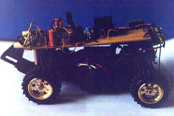
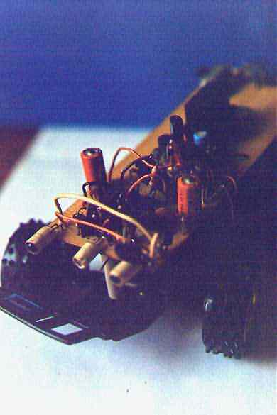
The circuit will be mounted according to the following photographs.
SOME TIPS ABOUT SENSOR ALINEMENT AND CALIBRATION
* ALINEMENT
IR emitters leds irradiate a cone of infra red light therefore some experimenting is necessary to determine position and best shrouding in order to prevent that the FT receptor located in the middle receives direct IR emissions.
In Fig 2 are shown the main beams of the IR emitters (in red) and the lateral beams (in orange). The FT photo transistor has a reception cone depicted in sky-blue. Note that direct lateral emissions of infra red light reach the FT. We don't want this direct type of illumination, what we want are the reflections of the main IR beams (in red) produced by an object ahead.
Fig 3 depicts how we may prevent lateral emission beams from reaching the FT. If we put some kind of sleeve or shroud around the emitter leds we may control how much this lateral beam will expand, i.e.: the angle of aperture.
Remember the four photographs of the car shown above? If you click on the "front view" photograph you'll see a close-up of the shrouded emitters. Certainly you may also shroud the FT.
All we have discussed relates to the horizontal plane, but similar considerations can be made considering the vertical plane. Precautions against ground reflection should be consider, i.e.: the angle from horizontal plane the IRs aim for.
* CALIBRATION
It's not very difficult to calibrate the PLL reception module, just follow the instructions:
According to Fig 4a the circuit is energized but the motor is turned off. Put an obstacle at about 4 inches ahead of IR emitters and slowly turn the PLL pot until the capture led turns on. Now the PLL is tuned; mark the pot value at which the capture was achieved.
As there may be harmonics of the main capture frequency, continue marking different positions at which the capture led turns on. Later, when we move farther away the obstacle, this points will disappear.
Now according to Fig 4b we repeat the process of Fig 4a but with the obstacle at position #2. Repeat the process at farther distances: i.e.: position #3.
You'll see that at greater distances from the sensors, the other marks in PLL pot disappear, just leaving only the main frequency f0.
ABOUT THE CIRCUIT
* The transmitting Module
Here's there's no big deal. while you continue reading this description (you may call the new window every time it's needed).
Let's start from the left: a NE 555 is configured as a astable oscillator running at 18 KHz. Its output (pin 3) goes into a transistor which drives the two IR leds. You may notice a 100 ohm trimmer to adjust IR intensity. This is useful if you want your batteries to run longer or if there's a lot of bouncing reflections from around that confuses the FT. A 220 uF electrolytic cap and a 1N4001 diode serve as decoupler to isolate the transmitting module, thus preventing the 18 KHz signal to propagate by the main +6 volt bus. You may select another value or even insert in parallel a 100 nF ceramic disc cap.
* The Reception Module
Here you have the phototransistor FT and an amplifier stage with some selectivity around 18 KHz, the received signal continues and enters the NE567 PLL (Phase Locked Loop). This integrated circuit works as follows: when the arriving signal has a frequency equal to the one programmed into the 567, pin 8 goes to ground. The central capture frequency f0 is programmed by the RC line (30 Kohm pot, 43 K resistor and 1 nF ceramic cap) between pins 5,6 and ground. Capacitors between pins 1 and 2 set the width of the frequency capture window, which means that the 567 will "capture" any frequency between f1 and f2.
The reception of a signal with different frequency than the 18 KHz selected in the PLL, keeps pin 8 at high (+6v). Upon reception and capture of a 18 kHz signal, pin 8 goes to ground thus turning the capture led on. The junction between the two 1 kohm resistors, initially at +6 volts now goes to approximately +4 volts (remember the 1.6 to 2 volt drop in the led when conducting). Now, with +4 volt at the base, the PNP transistor will be turned on (we need the base at least 0.7 volt below the +6 v line), enabling us to use this PNP transistor as a switch.
* The Timing Module
With the PNP transistor turned on, we have now an instant charge on the 10 uF electrolytic capacitor connected to the PNP collector. But this charge is applied to a 100 kohm resistor, thus generating a timing constant equal to 2xRxC. In our case about 2 seconds: This means the collector of the PNP will decay to ground in about 2 seconds. The next NPN transistor has its base connected to the PNP collector, so, when the PNP's collector suddenly displays +V, the NPN is turned on and will be on for the time selected in the RC constant.
This NPN drives a relay with 2 normal-close contacts. This relay will be energized for the time the RC and the NPN transistor timing circuit is programmed.
* The Relay-Motor Module
In this module the motor's supply is taken from +6 and +3 volt points. The relay contacts are connected in such a way as to invert the motor supply polarity, thus enabling motor reversion upon signal capture.
The relay is a PC-Mounted electromechanical relay, with a coil of 5 or 6vdc and contacts with a rating of less than 1 Amper (the motor draws less than 1 amper for sure). Is DPDT type (double pole, double throw). Radio Shack has many type of these, catalog number #900-2334, OEG brand, model OMI-SS-2-05D, about $2.50 each. See the following picture for details:
I used a PC mounted relay (miniature type also) Metaltex, model ML2RC1, 6 vdc coil (made in Japan).
Don't forget to identify and check the relay's contacts before wiring the system!
|
|
|
| |
Accurate LC Meter
Build your own Accurate LC Meter (Capacitance Inductance Meter) and start making your own coils and inductors. This LC Meter allows to measure incredibly small inductances making it perfect tool for making all types of RF coils and inductors. LC Meter can measure inductances starting from 10nH - 1000nH, 1uH - 1000uH, 1mH - 100mH and capacitances from 0.1pF up to 900nF. The circuit includes an auto ranging as well as reset switch and produces very accurate and stable readings. |
|
PIC Volt Ampere Meter
Volt Ampere Meter measures voltage of 0-70V or 0-500V with 100mV resolution and current consumption 0-10A or more with 10mA resolution. The meter is a perfect addition to any power supply, battery chargers and other electronic projects where voltage and current must be monitored. The meter uses PIC16F876A microcontroller with 16x2 backlighted LCD. |
|
|
|
60MHz Frequency Meter / Counter
Frequency Meter / Counter measures frequency from 10Hz to 60MHz with 10Hz resolution. It is a very useful bench test equipment for testing and finding out the frequency of various devices with unknown frequency such as oscillators, radio receivers, transmitters, function generators, crystals, etc. |
|
1Hz - 2MHz XR2206 Function Generator
1Hz - 2MHz XR2206 Function Generator produces high quality sine, square and triangle waveforms of high-stability and accuracy. The output waveforms can be both amplitude and frequency modulated. Output of 1Hz - 2MHz XR2206 Function Generator can be connected directly to 60MHz Counter for setting precise frequency output. |
|
|
|
BA1404 HI-FI Stereo FM Transmitter
Be "On Air" with your own radio station! BA1404 HI-FI Stereo FM Transmitter broadcasts high quality stereo signal in 88MHz - 108MHz FM band. It can be connected to any type of stereo audio source such as iPod, Computer, Laptop, CD Player, Walkman, Television, Satellite Receiver, Tape Deck or other stereo system to transmit stereo sound with excellent clarity throughout your home, office, yard or camp ground. |
|
USB IO Board
USB IO Board is a tiny spectacular little development board / parallel port replacement featuring PIC18F2455/PIC18F2550 microcontroller. USB IO Board is compatible with Windows / Mac OSX / Linux computers. When attached to Windows IO board will show up as RS232 COM port. You can control 16 individual microcontroller I/O pins by sending simple serial commands. USB IO Board is self-powered by USB port and can provide up to 500mA for electronic projects. USB IO Board is breadboard compatible. |
|
|
|
|
ESR Meter / Capacitance / Inductance / Transistor Tester Kit
ESR Meter kit is an amazing multimeter that measures ESR values, capacitance (100pF - 20,000uF), inductance, resistance (0.1 Ohm - 20 MOhm), tests many different types of transistors such as NPN, PNP, FETs, MOSFETs, Thyristors, SCRs, Triacs and many types of diodes. It also analyzes transistor's characteristics such as voltage and gain. It is an irreplaceable tool for troubleshooting and repairing electronic equipment by determining performance and health of electrolytic capacitors. Unlike other ESR Meters that only measure ESR value this one measures capacitor's ESR value as well as its capacitance all at the same time. |
|
Audiophile Headphone Amplifier Kit
Audiophile headphone amplifier kit includes high quality audio grade components such as Burr Brown OPA2134 opamp, ALPS volume control potentiometer, Ti TLE2426 rail splitter, Ultra-Low ESR 220uF/25V Panasonic FM filtering capacitors, High quality WIMA input and decoupling capacitors and Vishay Dale resistors. 8-DIP machined IC socket allows to swap OPA2134 with many other dual opamp chips such as OPA2132, OPA2227, OPA2228, dual OPA132, OPA627, etc. Headphone amplifier is small enough to fit in Altoids tin box, and thanks to low power consumption may be supplied from a single 9V battery. |
|
|
|
|
|
Arduino Prototype Kit
Arduino Prototype is a spectacular development board fully compatible with Arduino Pro. It's breadboard compatible so it can be plugged into a breadboard for quick prototyping, and it has VCC & GND power pins available on both sides of PCB. It's small, power efficient, yet customizable through onboard 2 x 7 perfboard that can be used for connecting various sensors and connectors. Arduino Prototype uses all standard through-hole components for easy construction, two of which are hidden underneath IC socket. Board features 28-PIN DIP IC socket, user replaceable ATmega328 microcontroller flashed with Arduino bootloader, 16MHz crystal resonator and a reset switch. It has 14 digital input/output pins (0-13) of which 6 can be used as PWM outputs and 6 analog inputs (A0-A5). Arduino sketches are uploaded through any USB-Serial adapter connected to 6-PIN ICSP female header. Board is supplied by 2-5V voltage and may be powered by a battery such as Lithium Ion cell, two AA cells, external power supply or USB power adapter. |
|
200m 4-Channel 433MHz Wireless RF Remote Control
Having the ability to control various appliances inside or outside of your house wirelessly is a huge convenience, and can make your life much easier and fun. RF remote control provides long range of up to 200m / 650ft and can find many uses for controlling different devices, and it works even through the walls. You can control lights, fans, AC system, computer, printer, amplifier, robots, garage door, security systems, motor-driven curtains, motorized window blinds, door locks, sprinklers, motorized projection screens and anything else you can think of. |
|
|
|