| |
Electrolytic capacitors are by far the electronic parts that suffer aging soonest. If you have any electronic equipment that over the years has degraded its performance, developed quirks, sometimes ending in complete failure, the chances are good that one or more electrolytic capacitors inside it have degraded, causing the problem. Electrolytic capacitors age in several ways: They can become electrically leaky, causing a DC current through them that can make them blow up. They can shift in capacitance value. But the most common way they degrade, by far, is by unduly increasing their equivalent series resistance, which is the undesired internal resistance that appears in series with the wanted capacitance at a given frequency.

The ESR of an electrolytic capacitor is normally just a small fraction of an Ohm for a high capacitance, low voltage capacitor (such as a 1000µF, 16V cap), and can be as high as two or three Ohm for a low capacitance, high voltage cap (1uF, 450V). When the capacitor ages, this resistance increases, and it often does so in such a dramatic way that the equipment completely ceases to function or even blows up semiconductors. It's very common to find capacitors that have degraded to 100 times their normal resistance, while their capacitance remains fine! On a typical capacitance meter they will measure close to their correct values, but they are completely bad! This is where the ESR meter comes in: It measures the equivalent series resistance of the capacitor, almost independently of its capacitance.
An additional beauty of an ESR meter is that in almost all cases it can check capacitors while they are in the circuit! This is so because a good capacitor would measure almost like a short circuit, and so any other parts connected in parallel will have minimal influence on the measurement. These are the features that make an ESR meter an irreplaceable tool for troubleshooting electronic equipment.
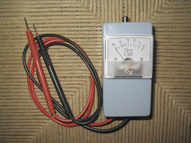
The design presented here works by applying a 50kHz, 200mV square wave to the capacitor under test, in series with a 10 Ohm resistor. The AC voltage appearing across that resistor is measured and displayed on a meter. So the whole thing is nothing else than a simple ohmmeter that uses ultrasonic AC for measurement instead of the usual DC used by every common ohmmeter. Since the Ac voltage used is so low, it does not make semiconductor junctions enter conduction, which further helps to make this meter suitable for checking capacitors mounted in a circuit.
One section of a dual low power operational amplifier is used as a square wave oscillator. A small ferrite core transformer is used to step down the voltage and provide the necessary low impedance output. A 10 Ohm resistor loads the output to absorb inductive spikes from the transformer, which could cause a false reading for low value capacitors. The other section of the op amp amplifies the signal that gets through the capacitor being tested, and its output is rectified and applied to a 50µA galvanometer through a calibration potentiometer. A small 5 Volt regulator maintains the supply constant while the instrument is being powered from anything between about 7 and 15 Volt. I power the meter from the 13.8V bus which I have in my workshop, but if you prefer, you can use a 9V battery instead, connected through a switch. The power consumption of this circuit is so low that a 9V battery should last at least 100 hours.
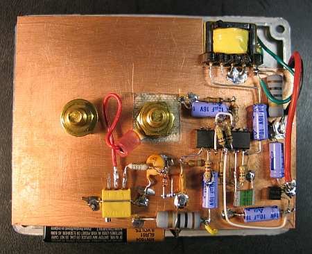
Building this ESR meter is simple and straightforward. I assembled the circuit on a scrap piece of project board, and used a small plastic box to install the board and the meter. The only part that could pose problems to inexperienced builders is the transformer. I made mine using an Amidon ferrite core, type EA-77-188, which is a tiny double-E core having a cross section of 22mm2, and external dimensions of about 19x16x5mm total. I used the nylon bobbin that Amidon delivers with it, wound a primary winding consisting of 400 turns of AWG #36 wire, and as secondary I wound 20 turns of AWG #26 wire. If you have a larger or smaller core, you can adjust the turn numbers in inverse proportion to the cross section area. The wire size isn't critical - the gauges I used are about 3 or 4 numbers thicker than necessary, while at the same time this bobbin has room for wire at least two numbers thicker than the ones I used. Thus, you can choose from about 6 different wire gauges for each winding, with negligible impact on the performance.
Considering that the transformer is so uncritical (because it runs at very low power), feel free to use any small ferrite core you have on hand, as long as it has no air gap. Dead PC power supplies and old monitors or TVs are great sources for such cores. Do not use an iron core, because it would probably have far too much loss at 50kHz.
The test leads are soldered into the circuit, and fixed in place using hot melt glue. Soldering them is much preferable over using any sort of connectors, because this meter easily detects resistance as low as 0.1 Ohm, and a connector can easily vary its resistance more than that! By the way, this set of test leads was bought as standard tester replacement leads, for very little money.
The meter is a reasonably good one rated at 50µA full scale, which I had on hand. If you find a cheap VU meter that works well, you can use it, of course. If you prefer to use a 100µA meter, change R11 to 50k. I used a trimpot for R11, but you might want to use a panel-mount potentiometer instead, which would allow fine adjusting the full-scale point if your meter happens to be unstable. If you use a cheap meter I would recommend this.
Calibration
Using the galvanometer's original scale, adjust its set screw for accurate zero position. With the circuit powered up, short the test leads together, and adjust R11 precisely for a full-scale reading. Now, take off the meter front cover, get a pencil and a few resistors in the range of 1 to 22 Ohm or so. Using the resistors as test objects, mark the corresponding deflections on the meter scale. It's your choice if you keep this crude hand-drawn scale indefinitely, or if you use it as a template to draw a definitive scale on the computer, print it and install it in the meter. I did the latter, and you can see the results on the top of this page.
Another version
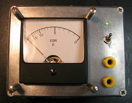
After setting up this page, I started getting lots of mail from other people who built their versions of the ESR meter. Curt Terwilliger, W6XJ, sent some high quality photos of his work. He found the box with the meter and banana jacks in his junk box, so needed just a little electronic tinkering to transform that thing into an ESR meter! The scale was redrawn, and the necessary guts installed behind.
He powered it from a 9V battery and even added a LED!
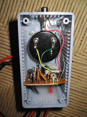
Curt used an existing transformer taken out of an old PC power supply. It has much lower impedance, and slightly lower turns ratio than my transformer, but works well enough.
Instead of the TL062, he used a TL084. That's a change I would not recommend, because the TL084 is not rated to work at the low voltage used here, so it's a matter of luck and tolerances that it works at all! Also, given the much higher saturation voltage of that opamp's output section, Curt had to modify the value of R8 to get a reasonable scaling on the meter. Before that, his instrument was driven into saturation, compressing the scale. But finally it worked for him, showing that builders can take quite a bit of artistic liberty and still get a useful result!
Curt used flat-style dead-bug construction on an unetched piece of PCB, obtaining a low profile circuit.
Using the meter
Take any capacitor with a value from about 1µF up, either loose or installed in a circuit, and connect the test leads to it. Polarity doesn't matter. Specially with high voltage caps, be sure the cap is discharged first. The meter will directly read the value of the equivalent series resistance of this capacitor. It should be pretty low, meaning that the meter should deflect to near full scale. Any large capacitor, say, over 100uF, should move the meter very close to full scale, often so close that you can't see the difference between the cap and a short circuit. If you read more than 1 Ohm or so, the capacitor has degraded, or was bad quality to start with. Small capacitors instead, say, 10µF and lower, could eventually have 1 or even 2 Ohm without being bad. Capacitors below 1uF will never reach very close to full scale, because these have enough reactance at 50kHz to be detected by the meter. As a reference, a good quality 1µF capacitor will read about 0.7 Ohm. while a good 220nF capacitor will read about 9 Ohm and a 100nF one will barely move the meter. So, you can consider this instrument as being reliable for any capacitor from 1µF up, and usable with increasing restrictions down to 100nF. Since almost all electrolytic capacitors have values from 1µF up, it's reasonable to advertise that this meter can be used for "essentially all" electrolytic capacitors, including tantalum caps.
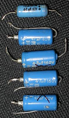
What difference do these two tantalum caps have? If you look at them, you will notice that they look alike almost as much as two eggs laid by the same hen. The two come from the same factory, and should belong to the same manufacturing batch. The two came in a bag of 20 equal ones I bought at a local store. Measured on a capacitance meter, both have almost exactly the same capacitance, very close to their rated 47µF. Measured with a common ohmmeter, both have essentially infinite insulation resistance. But when measuring their ESR with my newly built meter, I was in for a surprise: The one at right, like the other 18 caps not shown in this picture, has an ESR of about 0.2 Ohm, which is quite normal for a tantalum cap of this size. But the one on the left is a bad apple (or egg?) and has a whopping 15 Ohm ESR!!! It has a manufacturing defect, impossible to tell without measuring the ESR. If I had placed this capacitor in a circuit that exposes it to significant ripple current, it would have exploded, which is a trick tantalum caps just love to perform. Worse than that, if I had used it to filter a signal, it simply wouldn't have worked well, and I would have never suspected why my circuit didn't perform as calculated! After this surprise, I must advice you to test every component before putting it into a circuit, and never assume that a part that comes fresh from the factory is actually a good part!
The first true troubleshooting use for my new ESR meter was in rejuvenating my dear oscilloscope. That one is a 30 year old Tektronix, which I bought in bad condition 20 years ago and fixed. For those 20 years I hadn't done much to it, and over the years several minor functions had failed, but the biggest problem was that the trace had degraded to a fuzzy broad strip, its intensity modulated by hum and by the signal being measured! This really smelled like degrading electrolytic capacitors, no wonder after 30 years.
With my ESR meter I quickly found five electrolytic capacitors which had degraded a lot. Interestingly, four of them were of the same brand and can size, even if of two different values - probably there was a sealing problem! Of these capacitors, one had 4 Ohm ESR, one had 6 Ohm, one 7 Ohm, and the other two had such high ESR that the meter wouldn't even deflect! The other electrolytic caps in the oscilloscope were all still healthy, with ESR values well below one Ohm for most, and close to one Ohm for a few low capacitance, high voltage ones. I replaced the bad ones, and this gave me back a well defined and stable trace! Also one of the dead functions revived. The other dead functions were due to two open resistors, one value-shifted resistor, and two open transistors, which I found by conventional troubleshooting. After fixing all that, and spending two days completely realigning the instrument, it's again as good as new! But that's a matter for another web page...
|
|
|
| |
Accurate LC Meter
Build your own Accurate LC Meter (Capacitance Inductance Meter) and start making your own coils and inductors. This LC Meter allows to measure incredibly small inductances making it perfect tool for making all types of RF coils and inductors. LC Meter can measure inductances starting from 10nH - 1000nH, 1uH - 1000uH, 1mH - 100mH and capacitances from 0.1pF up to 900nF. The circuit includes an auto ranging as well as reset switch and produces very accurate and stable readings. |
|
PIC Volt Ampere Meter
Volt Ampere Meter measures voltage of 0-70V or 0-500V with 100mV resolution and current consumption 0-10A or more with 10mA resolution. The meter is a perfect addition to any power supply, battery chargers and other electronic projects where voltage and current must be monitored. The meter uses PIC16F876A microcontroller with 16x2 backlighted LCD. |
|
|
|
60MHz Frequency Meter / Counter
Frequency Meter / Counter measures frequency from 10Hz to 60MHz with 10Hz resolution. It is a very useful bench test equipment for testing and finding out the frequency of various devices with unknown frequency such as oscillators, radio receivers, transmitters, function generators, crystals, etc. |
|
1Hz - 2MHz XR2206 Function Generator
1Hz - 2MHz XR2206 Function Generator produces high quality sine, square and triangle waveforms of high-stability and accuracy. The output waveforms can be both amplitude and frequency modulated. Output of 1Hz - 2MHz XR2206 Function Generator can be connected directly to 60MHz Counter for setting precise frequency output. |
|
|
|
BA1404 HI-FI Stereo FM Transmitter
Be "On Air" with your own radio station! BA1404 HI-FI Stereo FM Transmitter broadcasts high quality stereo signal in 88MHz - 108MHz FM band. It can be connected to any type of stereo audio source such as iPod, Computer, Laptop, CD Player, Walkman, Television, Satellite Receiver, Tape Deck or other stereo system to transmit stereo sound with excellent clarity throughout your home, office, yard or camp ground. |
|
USB IO Board
USB IO Board is a tiny spectacular little development board / parallel port replacement featuring PIC18F2455/PIC18F2550 microcontroller. USB IO Board is compatible with Windows / Mac OSX / Linux computers. When attached to Windows IO board will show up as RS232 COM port. You can control 16 individual microcontroller I/O pins by sending simple serial commands. USB IO Board is self-powered by USB port and can provide up to 500mA for electronic projects. USB IO Board is breadboard compatible. |
|
|
|
|
ESR Meter / Capacitance / Inductance / Transistor Tester Kit
ESR Meter kit is an amazing multimeter that measures ESR values, capacitance (100pF - 20,000uF), inductance, resistance (0.1 Ohm - 20 MOhm), tests many different types of transistors such as NPN, PNP, FETs, MOSFETs, Thyristors, SCRs, Triacs and many types of diodes. It also analyzes transistor's characteristics such as voltage and gain. It is an irreplaceable tool for troubleshooting and repairing electronic equipment by determining performance and health of electrolytic capacitors. Unlike other ESR Meters that only measure ESR value this one measures capacitor's ESR value as well as its capacitance all at the same time. |
|
Audiophile Headphone Amplifier Kit
Audiophile headphone amplifier kit includes high quality audio grade components such as Burr Brown OPA2134 opamp, ALPS volume control potentiometer, Ti TLE2426 rail splitter, Ultra-Low ESR 220uF/25V Panasonic FM filtering capacitors, High quality WIMA input and decoupling capacitors and Vishay Dale resistors. 8-DIP machined IC socket allows to swap OPA2134 with many other dual opamp chips such as OPA2132, OPA2227, OPA2228, dual OPA132, OPA627, etc. Headphone amplifier is small enough to fit in Altoids tin box, and thanks to low power consumption may be supplied from a single 9V battery. |
|
|
|
|
|
Arduino Prototype Kit
Arduino Prototype is a spectacular development board fully compatible with Arduino Pro. It's breadboard compatible so it can be plugged into a breadboard for quick prototyping, and it has VCC & GND power pins available on both sides of PCB. It's small, power efficient, yet customizable through onboard 2 x 7 perfboard that can be used for connecting various sensors and connectors. Arduino Prototype uses all standard through-hole components for easy construction, two of which are hidden underneath IC socket. Board features 28-PIN DIP IC socket, user replaceable ATmega328 microcontroller flashed with Arduino bootloader, 16MHz crystal resonator and a reset switch. It has 14 digital input/output pins (0-13) of which 6 can be used as PWM outputs and 6 analog inputs (A0-A5). Arduino sketches are uploaded through any USB-Serial adapter connected to 6-PIN ICSP female header. Board is supplied by 2-5V voltage and may be powered by a battery such as Lithium Ion cell, two AA cells, external power supply or USB power adapter. |
|
200m 4-Channel 433MHz Wireless RF Remote Control
Having the ability to control various appliances inside or outside of your house wirelessly is a huge convenience, and can make your life much easier and fun. RF remote control provides long range of up to 200m / 650ft and can find many uses for controlling different devices, and it works even through the walls. You can control lights, fans, AC system, computer, printer, amplifier, robots, garage door, security systems, motor-driven curtains, motorized window blinds, door locks, sprinklers, motorized projection screens and anything else you can think of. |
|
|
|