| |
Solid State Relays are available almost everywhere these days, however they remain very expensive. Therefore, your efforts to build one yourself pays off. Especially since it only needs a handful components and the circuitry is simple and straightforward. A Solid State Relay is actually not a relay at all. There is no 'relay' present, just the electronics which does the switching. It works the same way as a relay; you can use a low voltage to switch a higher voltage or better. This 'relay' is positioned in between one of the 115/220V AC wires although it is common practice to leave the neutral wire the way it is and switch the phase or hot wire.
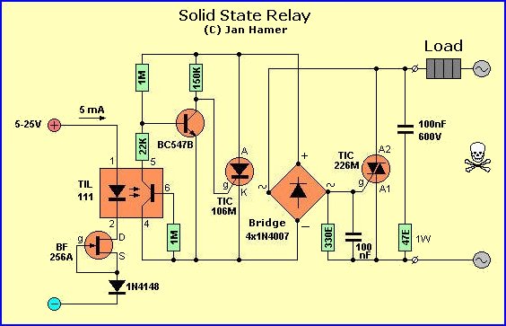
As long as there is no dc voltage present (left side of circuit diagram), the phototransistor within the TIL111 blocks and so no current is present. To make sure of that the base of the TIL111 is fed to the emitter (e) via an 1M resistor. This method prevents the base of transistor BC547B going low and thus remains biased 'on'. The collector is thus also low, and consequently the gate (g) of the TIC106M thyristor, which remains in the 'off' state. Through the 4-diode bridge rectifier circuit there is no current, except for the miniscule basis and collector current of the BC547B which is not enough over the 330 ohm resistor to switch on the TIC226M Triac. The current through the 'Load' is thus very very small.
With a certain input voltage, say 5 volt, the diode inside the TIL111 lights up and activates the phototransistor. The voltage drop over the 1Meg ohm resistor in series with the 22K resistor increases to a certain set point that it will block the BC547B transistor. The collector current at that moment will follow that of the AC voltage to a certain value which will activate the Thyristor. This creates a sufficient large voltage drop over the 330 ohm resistor to switch the Triac 'on'. The voltage over the Triac at that moment is only a couple volts so that the practically the whole 115/220 AC voltage is over the 'Load'.
The Triac is protected via the 100nF capacitor and the 47 ohm resistor, the 100nF capacitor over the 330 ohm resistor is to prevent unwanted biasing of the Triac created by small spikes. To create the possibility to switch this circuit with different voltages, a FET BF256A has been added. This FET acts like a current-source by means of connecting the source (s) with the gate (g). What this means is that this FET determines the current through the TIL111, no matter what voltage is put on the input (within certain tolerances of course). The diode 1N4148 is to protect the circuit in case of polarity reversal.
(Tony: The TIL111 is a so called 'optoisolator' with an NPN output and can be replaced with a NTE3042)
A good point of a circuit like this is the separation of the DC and AC voltages, so this circuit could be used in a variety of applications, up to approximately 1.5 KiloWatt, if you mount the Triac on a large cooling-rib.
The 'M' indicator noted on the Triac means it is a 600volt type, a 'D' stands for 400volt. So make sure you go for the M type.
The NTE replacements for this circuit are 600volt types which is more than sufficient for our 110/115VAC. Also, if you decide to make a pcb for this circuit, to create sufficient space between the AC lines and don't make these AC tracks too narrow.
Related Links
Downloads
Solid State Relays - Link
|
|
|
| |
Accurate LC Meter
Build your own Accurate LC Meter (Capacitance Inductance Meter) and start making your own coils and inductors. This LC Meter allows to measure incredibly small inductances making it perfect tool for making all types of RF coils and inductors. LC Meter can measure inductances starting from 10nH - 1000nH, 1uH - 1000uH, 1mH - 100mH and capacitances from 0.1pF up to 900nF. The circuit includes an auto ranging as well as reset switch and produces very accurate and stable readings. |
|
PIC Volt Ampere Meter
Volt Ampere Meter measures voltage of 0-70V or 0-500V with 100mV resolution and current consumption 0-10A or more with 10mA resolution. The meter is a perfect addition to any power supply, battery chargers and other electronic projects where voltage and current must be monitored. The meter uses PIC16F876A microcontroller with 16x2 backlighted LCD. |
|
|
|
60MHz Frequency Meter / Counter
Frequency Meter / Counter measures frequency from 10Hz to 60MHz with 10Hz resolution. It is a very useful bench test equipment for testing and finding out the frequency of various devices with unknown frequency such as oscillators, radio receivers, transmitters, function generators, crystals, etc. |
|
1Hz - 2MHz XR2206 Function Generator
1Hz - 2MHz XR2206 Function Generator produces high quality sine, square and triangle waveforms of high-stability and accuracy. The output waveforms can be both amplitude and frequency modulated. Output of 1Hz - 2MHz XR2206 Function Generator can be connected directly to 60MHz Counter for setting precise frequency output. |
|
|
|
BA1404 HI-FI Stereo FM Transmitter
Be "On Air" with your own radio station! BA1404 HI-FI Stereo FM Transmitter broadcasts high quality stereo signal in 88MHz - 108MHz FM band. It can be connected to any type of stereo audio source such as iPod, Computer, Laptop, CD Player, Walkman, Television, Satellite Receiver, Tape Deck or other stereo system to transmit stereo sound with excellent clarity throughout your home, office, yard or camp ground. |
|
USB IO Board
USB IO Board is a tiny spectacular little development board / parallel port replacement featuring PIC18F2455/PIC18F2550 microcontroller. USB IO Board is compatible with Windows / Mac OSX / Linux computers. When attached to Windows IO board will show up as RS232 COM port. You can control 16 individual microcontroller I/O pins by sending simple serial commands. USB IO Board is self-powered by USB port and can provide up to 500mA for electronic projects. USB IO Board is breadboard compatible. |
|
|
|
|
ESR Meter / Capacitance / Inductance / Transistor Tester Kit
ESR Meter kit is an amazing multimeter that measures ESR values, capacitance (100pF - 20,000uF), inductance, resistance (0.1 Ohm - 20 MOhm), tests many different types of transistors such as NPN, PNP, FETs, MOSFETs, Thyristors, SCRs, Triacs and many types of diodes. It also analyzes transistor's characteristics such as voltage and gain. It is an irreplaceable tool for troubleshooting and repairing electronic equipment by determining performance and health of electrolytic capacitors. Unlike other ESR Meters that only measure ESR value this one measures capacitor's ESR value as well as its capacitance all at the same time. |
|
Audiophile Headphone Amplifier Kit
Audiophile headphone amplifier kit includes high quality audio grade components such as Burr Brown OPA2134 opamp, ALPS volume control potentiometer, Ti TLE2426 rail splitter, Ultra-Low ESR 220uF/25V Panasonic FM filtering capacitors, High quality WIMA input and decoupling capacitors and Vishay Dale resistors. 8-DIP machined IC socket allows to swap OPA2134 with many other dual opamp chips such as OPA2132, OPA2227, OPA2228, dual OPA132, OPA627, etc. Headphone amplifier is small enough to fit in Altoids tin box, and thanks to low power consumption may be supplied from a single 9V battery. |
|
|
|
|
|
Arduino Prototype Kit
Arduino Prototype is a spectacular development board fully compatible with Arduino Pro. It's breadboard compatible so it can be plugged into a breadboard for quick prototyping, and it has VCC & GND power pins available on both sides of PCB. It's small, power efficient, yet customizable through onboard 2 x 7 perfboard that can be used for connecting various sensors and connectors. Arduino Prototype uses all standard through-hole components for easy construction, two of which are hidden underneath IC socket. Board features 28-PIN DIP IC socket, user replaceable ATmega328 microcontroller flashed with Arduino bootloader, 16MHz crystal resonator and a reset switch. It has 14 digital input/output pins (0-13) of which 6 can be used as PWM outputs and 6 analog inputs (A0-A5). Arduino sketches are uploaded through any USB-Serial adapter connected to 6-PIN ICSP female header. Board is supplied by 2-5V voltage and may be powered by a battery such as Lithium Ion cell, two AA cells, external power supply or USB power adapter. |
|
200m 4-Channel 433MHz Wireless RF Remote Control
Having the ability to control various appliances inside or outside of your house wirelessly is a huge convenience, and can make your life much easier and fun. RF remote control provides long range of up to 200m / 650ft and can find many uses for controlling different devices, and it works even through the walls. You can control lights, fans, AC system, computer, printer, amplifier, robots, garage door, security systems, motor-driven curtains, motorized window blinds, door locks, sprinklers, motorized projection screens and anything else you can think of. |
|
|
|